| CPC G02F 1/133605 (2013.01) [G02F 1/133504 (2013.01); G02F 1/133524 (2013.01); G02F 1/133533 (2013.01); G02F 1/133536 (2013.01); G02F 1/133607 (2021.01)] | 16 Claims |

|
1. A backlight for providing illumination to a liquid crystal panel, comprising:
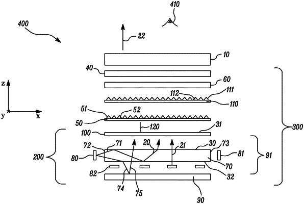
an extended light source adapted to emit light through an emission surface thereof;
a reflective polarizer disposed on the extended light source, such that for substantially normally incident light and for at least a first wavelength in a range from about 420 nm to about 650 nm, the reflective polarizer reflects at least 60% of the incident light having a first polarization state and transmits at least 60% of the incident light having an orthogonal second polarization state;
a first prismatic film disposed between the extended light source and the reflective polarizer and comprising a structured major surface comprising a plurality of substantially parallel first linear prisms extending along a first direction and arranged in an orthogonal second direction; and
a retarder layer disposed between the reflective polarizer and the first prismatic film, such that for substantially normally incident light at a wavelength of about 550 nm, the retarder layer has a retardance nW, where n is an integer ≥1 and W is between about 160 nm and about 300 nm, wherein light emitted by the backlight at zero and sixty degrees with respect to a line normal to the emission surface has respective color coordinates (x1, y1) and (x2, y2) in CIE 1931 chromaticity coordinate system in a white region, wherein x1 and x2 are different by less than about 0.0051, and y1 and y2 are different by less than about 0.01.
|