| CPC G02B 27/646 (2013.01) [G03B 11/04 (2013.01); H01F 7/16 (2013.01); H04N 23/68 (2023.01); H01F 7/08 (2013.01)] | 20 Claims |

|
1. A camera module comprising:
a printed circuit board;
a first image sensor disposed on the printed circuit board;
a first base disposed on the printed circuit board;
a first cover member disposed on the first base;
a first bobbin disposed in the first cover member;
a first housing disposed between the first cover and the first bobbin;
a first coil disposed on the first bobbin;
a first magnet disposed between the first bobbin and the first cover member;
a first lens barrel coupled with the first bobbin;
a first lens disposed in the first lens barrel;
a light shielding member disposed between the first image sensor and the first lens; and
a support part coupled with an inner peripheral surface of the lens barrel and disposed on a lower surface of a lowermost lens of the first lens,
wherein the light shielding member is directly disposed on the lower surface of the lowermost lens of the first lens,
wherein the first cover member comprises first and second side plates opposite to each other, and third and fourth side plates opposite to each other,
wherein the first magnet comprises a first magnet unit disposed between the bobbin and the first side plate, a second magnet unit disposed between the bobbin and the second side plate, and a third magnet unit disposed between the bobbin and the third side plate,
wherein the third magnet unit is smaller than each of the first magnet unit and the second magnet unit,
wherein each of the first magnet unit and the third magnet unit has a thickness measured from an inner lateral surface of the corresponding magnet unit facing the first coil to an outer lateral surface of the corresponding magnet unit,
wherein the thickness of the third magnet unit is smaller than the thickness of the first magnet unit,
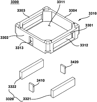
wherein the first housing comprises a third magnet unit reception part inwardly recessed from an outer lateral surface of the first housing,
wherein at least a part of the third magnet unit is disposed on the third magnet unit reception part, and
wherein a part of the first housing is disposed between the third magnet unit and the first coil in a direction in which the third magnet unit faces the first coil.
|