| CPC G01S 7/52033 (2013.01) [G01S 7/52046 (2013.01); G01S 15/8925 (2013.01); G01S 7/5208 (2013.01)] | 13 Claims |

|
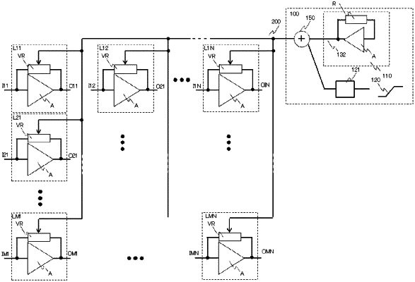
1. An ultrasonic probe transmitting an ultrasonic wave to a diagnostic organ and receiving a reception signal that is a reflected wave, the ultrasonic probe comprising:
a plurality of transducers;
a plurality of low-noise amplifier circuits individually corresponding to the plurality of transducers, wherein each of the plurality of low-noise amplifier circuits has a variable resistor negative feedback unit making a resistance value variable by a voltage signal inputted to a control terminal of the variable resistor negative feedback unit; and
a control circuit,
wherein the control circuit includes:
a dummy circuit generating a bias voltage of the variable resistor negative feedback unit in each of the plurality of the low-noise amplifier circuits; and
an adding circuit outputting an added signal generated by adding the bias voltage from the dummy circuit and a control signal increasing or decreasing with a lapse of time, and wherein
each of the plurality of low-noise amplifier circuits input an output of the adding circuit to the control terminal of the variable resistor negative feedback unit to perform variable control on a gain of the low-noise amplifier circuit,
the control circuit further includes a floating voltage circuit,
the floating voltage circuit has a variable resistor making a resistance value variable by an electrical signal inputted to a control terminal,
the floating voltage circuit feeds a direct current signal to the control terminal of the variable resistor and carries a direct current to the variable resistor to generate a floating voltage, and
the control circuit inputs a signal that has been level shifted by the floating voltage based on the added signal output of the adding circuit to the control terminal of the variable resistor negative feedback unit in each of the plurality of low-noise amplifier circuits.
|