| CPC G01R 27/14 (2013.01) [G01R 27/00 (2013.01); H03F 3/45179 (2013.01); H03M 1/34 (2013.01); H03M 3/04 (2013.01)] | 19 Claims |

|
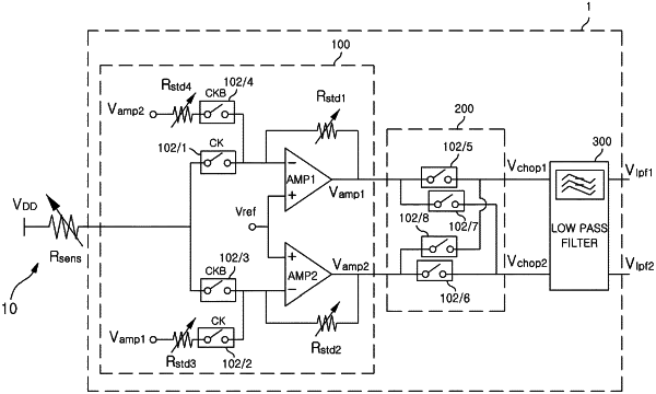
1. A differential mode converter comprising:
an input mode converter configured to convert an input voltage input in a single-ended mode into a first differential voltage and a second differential voltage to be output based upon a first clock signal and a second clock signal, wherein the input mode converter further comprises:
a first amplifier comprising:
a first input terminal to which a signal is inputted through a target resistance,
a second input terminal to which the reference voltage is inputted,
a first output terminal which outputs the first differential voltage;
a second amplifier comprising:
a third input terminal to which a signal is inputted through the target resistance,
a fourth input terminal to which the reference voltage is inputted, and
a second output terminal which outputs the second differential voltage, the first clock signal and the second clock signal have opposite logic states, and the first differential voltage and the second differential voltage are symmetric with respect to a reference voltage and have a form of a square wave; and
a chopper configured to receive the first differential voltage and the second differential voltage, wherein a first chopping voltage and a second chopping voltage are based on the first differential voltage and the second differential voltage to output the first chopping voltage and the second chopping voltage, and the first chopping voltage and the second chopping voltage are symmetric with respect to the reference voltage and have a DC voltage.
|