| CPC G01C 19/5712 (2013.01) [G01C 19/5762 (2013.01); G01D 1/16 (2013.01); G01D 1/18 (2013.01); G01D 3/08 (2013.01); G01D 5/24 (2013.01); G01H 11/06 (2013.01); G01H 13/00 (2013.01); G01R 31/2644 (2013.01); G01R 31/282 (2013.01); G01R 31/2829 (2013.01); G01R 31/2856 (2013.01); G01R 31/3187 (2013.01); H04B 2001/0491 (2013.01); H04B 14/002 (2013.01)] | 5 Claims |

|
1. A microelectromechanical gyroscope which comprises
one or more Coriolis masses which are coupled to a drive transducer which actuates the one or more Coriolis masses into primary oscillation movement at a primary oscillation frequency Fprim, wherein the one or more Coriolis masses are configured to be actuated into secondary oscillation movement by the Coriolis force when the gyroscope undergoes angular rotation, and the secondary oscillation mode has a secondary resonant frequency Fsec,
a drive sensing circuit comprising a drive sensing transducer which is coupled to measure the primary oscillation movement of the one or more Coriolis masses and configured to generate a drive tracking signal which tracks the primary oscillation movement of the one or more Coriolis masses,
a readout circuit comprising a sense transducer which is coupled to measure the secondary oscillation movement of the one or more Coriolis masses and configured to generate a sense signal which tracks the secondary oscillation movement of the one or more Coriolis masses,
a force-feedback system comprising a force-feedback transducer coupled to the one or more Coriolis masses and a force feedback circuit coupled to the force-feedback transducer,
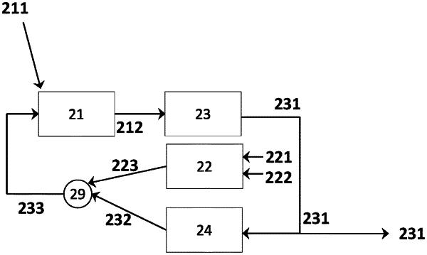
wherein the force-feedback circuit comprises a first sideband modulator which is configured to receive the drive tracking signal as input, to modulate the drive tracking signal with a first modulation frequency and to output a first sideband signal,
wherein the force-feedback circuit further comprises a second sideband modulator which is configured to receive the first sideband signal as input, to modulate the first sideband signal with a second modulation frequency and to output a second sideband signal,
and the force-feedback circuit further comprises a summing element which is configured to receive the sense signal and the second sideband signal as input, to sum them together to generate a force-feedback signal and to output the force-feedback signal to the force-feedback transducer,
and wherein the gyroscope further comprises a self-test circuit coupled to the readout circuit, and the self-test circuit comprises a multiplier which is configured to receive the sense signal and the drive tracking signal as input, multiply them with each other and output a self-test signal to a low-pass filter, and the low-pass filter is configured to output a low-pass filtered self-test signal to a control unit,
and wherein the self-test circuit further comprises a first sideband demodulator and a second sideband demodulator, and either the sense signal or the drive tracking signal is demodulated in the first sideband demodulator at the first modulation frequency before entering the multiplier, and either the sense signal or the drive tracking signal is demodulated in the second sideband demodulator at the second modulation frequency before entering the multiplier,
and the control unit is configured to compare the amplitude of the low-pass filtered self-test signal to a predetermined lower threshold value and to a predetermined upper threshold value and to generate a self-test failure indicator if the low-pass filtered self-test signal is below the lower threshold value or above the upper threshold value.
|