| CPC G01B 11/272 (2013.01) [G01B 11/14 (2013.01); G02B 27/0101 (2013.01); G02B 27/0179 (2013.01); G02B 27/646 (2013.01); G02B 27/648 (2013.01); G06T 7/70 (2017.01); G02B 2027/0138 (2013.01); G02B 2027/0183 (2013.01); G02B 2027/0198 (2013.01)] | 7 Claims |

|
1. A system comprising:
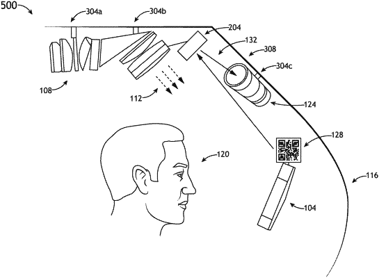
a head-up display comprising a combiner and a relay lens assembly;
an illuminated reticle spatially coupled to the combiner, wherein a movement of the combiner results in a commensurate movement of the illuminated reticle;
an optical sensor;
a mirror spatially coupled to the relay lens assembly and configured to reflect light from the illuminated reticle to the optical sensor, wherein the optical sensor is optically coupled to the mirror, wherein the optical sensor is configured to detect a light pattern emitted from the illuminated reticle; and
a control module communicatively coupled to the optical sensor comprising one or more processors and a memory, wherein the control module is configured to:
receive an input from the optical sensor;
determine a position of the combiner relative to the relay lens assembly based on the received input; and
generate an output based on a determined position of the combiner relative to the relay lens assembly.
|