| CPC F23D 14/586 (2013.01) [F23D 14/02 (2013.01); F23D 14/74 (2013.01); F23D 2900/14003 (2013.01)] | 16 Claims |

|
1. A flame-hole structure of a combustion apparatus, wherein the flame-hole structure has a plurality of flame-holes for forming a flame, the flame-hole structure comprising:
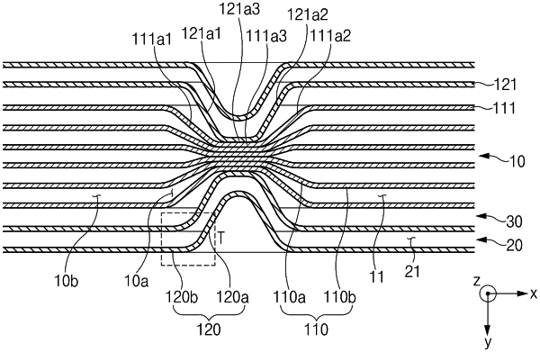
a lean flame-hole part having a plurality of lean flame-holes arranged along a width direction perpendicular to a jetting direction of lean gas as flame-holes through which the lean gas is jetted; and
a rich flame-hole part having a pair of rich flame-holes provided on opposite sides of the lean flame-hole part with respect to the width direction as flame-holes through which rich gas is jetted,
wherein the lean flame-hole part includes a first region in which widths of the lean flame-holes along the width direction are constant along a lengthwise direction perpendicular to the jetting direction and the width direction and second regions provided on opposite sides of the first region along the lengthwise direction, the widths of the lean flame-holes along the width direction being narrower in the second regions than in the first region,
wherein the lean flame-hole part and the rich flame-hole part are brought into close contact with each other in at least part of the second regions
wherein the lean flame-hole part further includes a plurality of lean plates disposed to be spaced apart from each other at a predetermined interval while facing each other along the width direction, and the lean flame-holes are formed in separation spaces between the lean plates,
wherein the rich flame-hole part further includes a plurality of rich plates disposed to be spaced apart from each other at a predetermined interval while facing each other along the width direction, and the rich flame-holes are formed in separation spaces between the rich plates, wherein the plurality of lean plates include a bending portion bent toward the center of the lean flame-hole part along the width direction to form the second regions and lean plate horizontal-portions extending from opposite ends of the bending portion along a direction parallel to the lengthwise direction,
wherein the plurality of rich plates include a protruding portion protruding toward the bending portion to correspond to the bending portion and rich plate horizontal-portions extending from opposite ends of the protruding portion along the direction parallel to the lengthwise direction,
wherein a protruding portion of a first rich plate located in the innermost position with respect to the width direction among the plurality of rich plates is brought into close contact with at least part of a bending portion of a first lean plate located in the outermost position with respect to the width direction among the plurality of lean plates,
wherein the protruding portion of the first rich plate includes a first inclined surface and a second inclined surface extending from the adjacent rich plate horizontal-portions so as to be inclined toward the center of the lean flame-hole part along the width direction and a first horizontal surface extending along the direction parallel to the lengthwise direction to connect distal ends of the first inclined surface and the second inclined surface,
wherein the bending portion of the first lean plate includes a third inclined surface and a fourth inclined surface extending from the adjacent lean plate horizontal-portions so as to be inclined toward the center of the lean flame-hole part along the width direction and a second horizontal surface extending along the lengthwise direction to connect distal ends of the third inclined surface and the fourth inclined surface, and
wherein the first horizontal surface is brought into contact with the second horizontal surface.
|