| CPC F15B 15/02 (2013.01) [F03C 2/08 (2013.01); F04C 15/0061 (2013.01); F04C 15/0084 (2013.01); F16D 57/002 (2013.01); F16F 9/532 (2013.01); F16F 9/535 (2013.01); F16H 61/44 (2013.01); F16H 61/444 (2013.01); F04C 2240/81 (2013.01); F04C 2270/0525 (2013.01); F15B 2211/40 (2013.01); F15B 2211/4053 (2013.01); F15B 2211/715 (2013.01)] | 18 Claims |

|
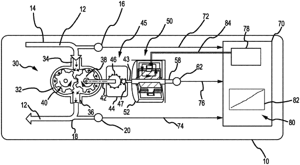
1. A hydraulic fluid system, comprising:
a hydraulic motor including an output shaft;
a reduction gear box having a first side and an opposing second side, the reduction gear box being coupled to the output shaft at the first side and coupled to a reduction shaft at the second side, wherein the output shaft has a first diameter and the reduction shaft has a second diameter, the second diameter being smaller than the first diameter; and
a magneto-rheological fluid (MRF) brake coupled to the reduction shaft.
|