| CPC F04D 3/02 (2013.01) [F04D 13/06 (2013.01); F28D 7/026 (2013.01); F28F 13/12 (2013.01); F28F 21/062 (2013.01); H02K 44/06 (2013.01); H05K 7/14337 (2022.08); H05K 7/20236 (2013.01); H05K 7/20272 (2013.01); H05K 7/20872 (2013.01); H05K 7/20927 (2013.01)] | 15 Claims |

|
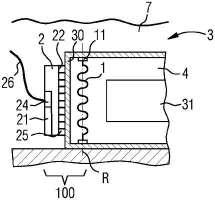
1. A liquid circulation system comprising:
a rotor located within a tank,
an electric component accommodated within the tank,
a power unit comprising a stator having a plurality of coils, a control unit and an electric terminal box, the power unit is attached outside the tank, and
an exterior tank wall of the tank that is non-magnetic and that is located next to the rotor and to the stator between the rotor and the stator, the power unit is attached on the exterior tank wall,
wherein
the tank is configured as a sub-sea component,
the rotor faces the electric component so that there is no exterior tank wall between the rotor and the electric component,
an axis (R) of rotation of the rotor is in parallel with the exterior tank wall next to the rotor,
the rotor is configured to be rotated by the stator through the exterior tank wall by means of a varying electromagnetic field driven by the stator to circulate a liquid within the tank and a paddle portion of the rotor is configured to rotate around the axis (R) of rotation is distant from the exterior tank wall,
the coils of the stator are arranged along the axis (R) of rotation of the rotor so that the coils are arranged in a linear manner along a straight line, and
at least a driving portion of the rotor is of helical shape.
|