| CPC E04D 13/174 (2013.01) [E04D 13/176 (2013.01); E04D 13/17 (2013.01); F24F 13/08 (2013.01)] | 24 Claims |

|
1. A vent comprising:
a top panel having a bottom surface, a top surface, a central portion and side portions terminating at lateral edges;
wherein the top panel is configured to be installed along a slot formed along a ridge or a hip of a roof to provide ventilation;
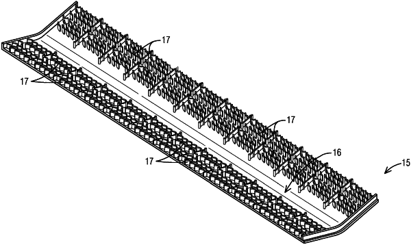
a plurality of baffle arrays positioned along the top panel between the central portion and the lateral edges thereof, the baffle arrays each comprising a plurality of spaced vanes projecting from the bottom surface of the top panel; and
at least one filler strip extending along at least a portion of at least one of the baffle arrays, the filler strip comprising a material configured to conform to a surface of portions of the roof adjacent the slot when the hip vent is installed on the roof;
wherein the plurality of baffle arrays further comprises at least two laterally spaced baffle arrays arranged between the central portion and each of the lateral edges of the top panel;
wherein each baffle array comprises at least two rows each having at least two laterally spaced vanes;
wherein the vanes of the baffle arrays are spaced and arranged such that no uninterrupted path for water, snow, debris, or a combination thereof, is defined through the baffle arrays;
wherein the vanes of at least some of the baffle arrays each comprise a first end located nearer the central portion of the top panel, a second end located nearer an adjacent lateral edge of the top panel, and a curved configuration arcing downwardly and outwardly toward an adjacent lateral edge of the top panel;
wherein the second ends of the vanes are arranged along the bottom surface of the top panel so as to laterally overlap the first ends of adjacent vanes of an adjacent downslope row of vanes such that when the top panel is installed along the roof, water, snow, debris, or combination thereof, encountering the vanes is redirected away from the slot formed along the ridge or hip of the roof and toward the lateral edges of the top panel.
|