| CPC B41J 2/17526 (2013.01) [B41J 2/175 (2013.01); B41J 2/17513 (2013.01); B41J 2/1752 (2013.01); B41J 2/1753 (2013.01); B41J 2/17553 (2013.01); B41J 2/17566 (2013.01)] | 20 Claims |

|
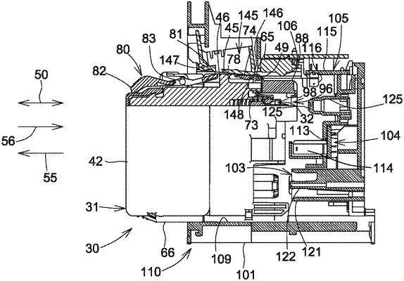
1. A printing fluid cartridge, comprising:
a front side, and a rear side positioned opposite the front side with respect to a front-rear direction;
an upper side, and a lower side positioned opposite the upper side with respect to an up-down direction which is perpendicular to the front-rear direction;
a printing fluid supply portion positioned at the front side;
a spring positioned within a cavity that extends from an opening at the front side of the printing fluid cartridge in the front-rear direction;
a circuit board including a plurality of electrodes, the circuit board being positioned at the upper side;
a pivotable member positioned at the upper side between the circuit board and the rear side in the front-rear direction, and configured to pivot about a pivot point;
an engagement surface disposed between the pivotable member and the circuit board at the upper side, the engagement surface facing rearward and extending in the up-down direction; and
a top wall at the upper side, wherein the top wall faces upward in the up-down direction,
wherein a distance in the up-down direction from the lower side to the spring exceeds a distance in the up-down direction from the lower side to the printing fluid supply portion,
wherein a distance in the up-down direction from the lower side to the pivot point, exceeds a distance in the up-down direction from the lower side to the spring,
wherein the pivotable member includes a front portion extending in the front-rear direction from the pivot point toward the circuit board, and a rear portion extending in the front-rear direction from the pivot point toward the rear side,
wherein the pivotable member is pivotable between a first position in which the front portion of the pivotable member is at its furthest point from the lower side and a second position in which the front portion of the pivotable member is at its closest point to the lower side,
wherein the top wall contacts the front portion of the pivotable member from below the front portion of the pivotable member when the pivotable member is in the second position, and
wherein when the pivotable member pivots from the second position to the first position, the front portion of the pivotable member moves away from the top wall.
|