| CPC B29C 48/08 (2019.02) [B29C 48/0018 (2019.02); B29C 48/305 (2019.02); B29C 48/914 (2019.02); B29C 48/92 (2019.02); B29C 55/02 (2013.01); B29C 2948/92114 (2019.02); B29C 2948/92209 (2019.02); B29C 2948/92466 (2019.02); B29C 2948/92961 (2019.02)] | 16 Claims |

|
1. A line for producing a cast film for a film stretching unit, comprising:
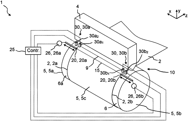
a slot die, a chill roll with a chill roll shell extending between two opposite end faces of the chill roll, an electrode assembly, a high-voltage generation device, an insulator assembly, a sensor device and a control device are provided;
the slot die is configured to output a plastic melt onto an impingement area of the surface of the rotating chill roll, thereby forming a cast film;
at a removal area of the chill roll, which is arranged offset from the impingement area in the direction of rotation of the chill roll, the cast film can be removed from the surface of the chill roll and fed directly or indirectly to a film stretching unit;
the electrode assembly is arranged between the impingement area and the removal area of the chill roll;
the electrode assembly extends at a distance from the surface of the chill roll at least in a partial length of the chill roll between the two end faces of the chill roll;
the high-voltage generation device is configured to generate and apply a high voltage to the electrode assembly;
the insulator assembly is arranged between the electrode assembly and the chill roll shell of the chill roll;
the sensor device is configured to continuously detect the left and right cast film edge;
the control device is configured, in order to avoid voltage flashovers between the electrode assembly and the chill roll, to move the insulator assembly on the basis of the detected left cast film edge and the detected right cast film edge in such a way that the insulator assembly is arranged:
a) between the left end face of the chill roll and the left cast film edge; and
b) between the right end face of the chill roll and the right cast film edge; and
a sensor area of the sensor device is provided downstream of the slot die and upstream of the electrode assembly in the output direction of the cast film, and wherein
the insulator assembly comprises a left insulator element and right insulator element;
the left insulator element is movable from the left end face of the chill roll toward the center of the chill roll and vice versa;
the right insulator element is moveable from the right end face of the chill roll toward the center of the chill roll and vice versa;
the sensor device comprises a left sensor arrangement for detecting the left cast film edge and a right sensor arrangement for detecting the right case film edge;
the left sensor arrangement is movable synchronously with the left insulator element, and
the right sensor arrangement is movable synchronously with the right insulator element.
|