| CPC B29B 7/426 (2013.01) [B29B 7/885 (2013.01); B29B 17/00 (2013.01); B29B 17/0026 (2013.01); B29B 17/04 (2013.01); B29C 48/277 (2019.02); B29C 48/385 (2019.02); B29C 48/507 (2019.02); B29C 48/845 (2019.02)] | 5 Claims |

|
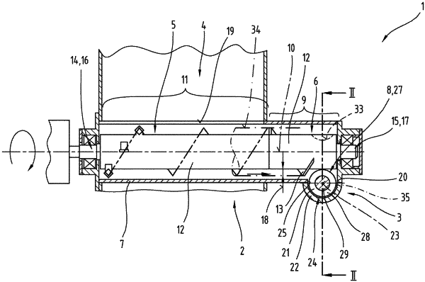
1. A processing plant (1) for processing thermoplastic material for the recycling thereof, comprising
a feed device (4),
a processing unit (2) having
a hollow-cylindrically designed housing (7),
a shaft body (12) with a comminuting device (5) arranged or formed on the shaft body (12) and a conveying device (6) adjoining the comminuting device (5) in a conveying direction, the conveying device (6) comprising at least one first screw flight (13),
wherein the shaft body (12) defines a first longitudinal axis (10),
wherein the first screw flight (13) projects beyond the shaft body (12) in a radial direction by a first projection (18), and the first projection (18) defines a first circular ring surface having an outer first envelope (34), wherein a ring width of the first circular ring surface corresponds to the first projection (18),
wherein the conveying device (6) defines a first conveying section (9) in an axial direction of the shaft body (12),
wherein the shaft body (12) is accommodated in the housing (7) and is rotatably mounted on its first shaft end (14), by means of a first bearing arrangement (16), and on its second shaft end (15), which is spaced apart from the first shaft end in an axial direction, by means of a second bearing arrangement (17) on the housing (7), and
wherein the housing (7) has, in a region of the comminuting device (5), at least one feed opening (19) open towards the feed device (4),
an extrusion device (3) having
an extruder housing (22),
at least one extruder screw (21) comprising a screw base body (29) and at least one further screw flight (28),
wherein the at least one further screw flight (28) of the extruder screw (21) defines an outer further envelope (35),
wherein the extruder screw (21) is accommodated in the extruder housing (22) and defines a further longitudinal axis (23), and
wherein the at least one extruder screw (21) defines a second conveying section (24) and the extrusion device (3) is arranged behind, when viewed in the conveying direction, the processing unit (2),
a transfer region (8) with a discharge opening (20) out of the housing (7) and a fill opening (25) into the extruder housing (22), wherein the transfer region (8) is arranged in an end section of the first conveying section (9) of the conveying device (6), and the first conveying section (9) is flow-connected to the second conveying section (24) in the transfer region (8), and
a recess (33) in the shaft body (12), wherein the recess (33) is formed continuously across a circumference of the shaft body (12) and has a cross-section viewed in an axial section, designed to be slightly greater in a section facing the extruder screw (21) than the outer further envelope (35) defined by the further screw flight (28),
wherein, with respect to a projection onto a horizontal plane, the first longitudinal axis (10) and the further longitudinal axis (23) are oriented such that they intersect in the transfer region (8),
wherein at least the further screw flight (28) of the extruder screw (21), when viewed in an axial projection direction toward the first longitudinal axis (10) of the shaft body (12) protrudes toward the first longitudinal axis (10), into the first circular ring surface defined by the first screw flight (13) with its first projection (18),
wherein the first screw flight (13) ends, when viewed in a direction of the first longitudinal axis (10), before the outer further envelope (35) defined by the further screw flight (28), and
wherein a portion of the screw base body (29) of the extruder screw (21) protrudes into the first circular ring surface defined by the first projection (18) of the first screw flight (13).
|