| CPC B25J 13/086 (2013.01) [B25J 9/1687 (2013.01); B25J 13/085 (2013.01); B25J 15/026 (2013.01); E04G 21/22 (2013.01)] | 20 Claims |

|
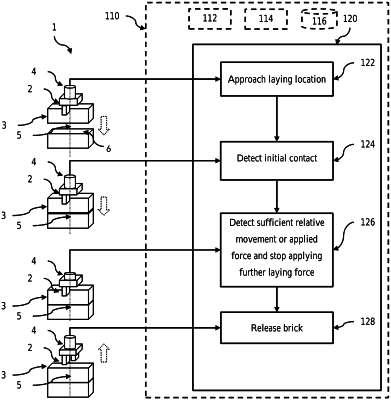
1. A gripping apparatus for controllably placing an object, the gripping apparatus including:
a gripper assembly mounted to a robot arm via a connector body, the gripper assembly including a housing that supports one or more gripper drive assemblies operatively coupled to a pair of opposing gripping clamps configured to grip and release an object in response to one or more gripper drive control signals, and in use the robot arm is configured to drive the gripper assembly along a placement axis towards a placement surface via the connector body;
a sensor configured to either measure a relative movement between the gripper assembly and the connector body in a direction aligned with the placement axis or to measure a force between the gripper assembly and the connector body in a direction aligned with the placement axis, wherein the sensor generates a sensor output signal based on the measurement; and,
a controller configured to send a stop signal to the robot arm to stop further drive of the gripper assembly along the placement axis when the sensor output signal indicates the measured relative movement or measured force exceeds a predefined threshold,
wherein either the housing includes a cavity that extends in a direction aligned with the placement axis and encompasses a flange portion of the connector body or the connector body includes a cavity that extends in a direction aligned with the placement axis and encompasses a flange portion of the housing; and, the sensor is configured to measure the relative movement of the flange portion within the cavity in the direction aligned with the placement axis.
|