| CPC B23K 26/0823 (2013.01) [B23K 26/362 (2013.01); B44B 3/04 (2013.01); B44B 3/065 (2013.01); B44B 2700/025 (2013.01)] | 20 Claims |

|
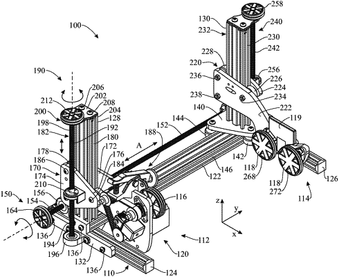
1. A rotary laser engraving device for retaining and rotating objects to be engraved, the rotary laser engraving device comprising:
a frame comprising a central bar arranged in a longitudinal direction, a first support post extending vertically upward relative to the central bar, and a second support post extending vertically upward relative to the central bar;
a first support assembly carried by the first support post for supporting a first end of the object to be engraved;
wherein the first support assembly includes a first set of rollers engaged with a motor assembly to rotate the object to be engraved;
wherein the first support assembly includes a gripping mechanism configured to abut against an inner surface of the object to be engraved;
a second support assembly carried by the second support post and including a second set of rollers for supporting a second end of the object to be engraved;
wherein the first set of rollers and the second set of rollers are offset diagonally from the central bar of the frame;
a longitudinal adjustment mechanism carried by the frame and configured to move at least one of the first support post and the second support post in the longitudinal direction along the central bar to vary a longitudinal separation between the first set of rollers and the second set of rollers; and
at least one vertical adjustment mechanism carried by the frame and configured to move at least one of the first support assembly and second support assembly vertically along the first support post and second support post, respectively, to vary a vertical separation between the first set of rollers and the second set of rollers.
|