| CPC B23B 51/00 (2013.01) [B23B 51/0003 (2022.01); B23B 51/0004 (2022.01); B23B 2251/02 (2013.01); B23B 2251/50 (2013.01)] | 27 Claims |

|
1. A modular drill apparatus comprising:
a shank including a pocket defined by a bottom and sidewalls which extend from the bottom to a distal opening of the pocket, the shank including a cylindrical post centrally disposed at the bottom of the pocket, the cylindrical post including a distal end with an unlock interface,
a cutting tip including a lower portion, an upper portion and a channel therebetween, the channel spanning across the cutting tip perpendicular to a longitudinal axis of the modular drill apparatus, the lower portion including a central bore which receives the cylindrical post for symmetrically supporting the cutting tip within the pocket and allowing repositioning of the cutting tip within the pocket along the longitudinal axis; and
an insert assembly interfitted within the channel, the insert assembly being expandable/retractable along a channel axis of the channel, the insert assembly including chamfered surfaces at opposite ends thereof, respectively, and a ramp;
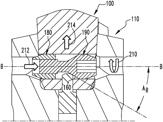
wherein the shank includes a pair of openings therethrough at opposite sides of the shank, the openings including lock interfaces at distal-most portions thereof adjacent to opposite ends of the channel, respectively, the shank and the cutting tip being shaped such that when the cutting tip is received within the pocket the openings generally coalign with the channel at the opposite ends thereof, respectively, one of the openings accommodating access to the insert assembly by a tool for adjustably expanding the insert assembly extending the opposite ends of the insert assembly into the openings bringing the chamfered surfaces into contact with the lock interfaces which are configured/angled such that the cutting tip and insert assembly together translate toward the bottom of the pocket providing an interference fit between the cutting tip and the sidewalls and for adjustably retracting the insert assembly bringing the ramp into contact with the unlock interface, the ramp and the unlock interface being configured/angled such that responsive to retracting the opposite ends of the insert assembly the cutting tip and insert assembly together translate/reposition a sufficient amount/distance away from the bottom of the pocket to release or disengage the cutting tip from the shank by overcoming the interference fit between the cutting tip and the sidewalls.
|