| CPC B23B 1/00 (2013.01) [B29C 66/0326 (2013.01); B29C 66/7212 (2013.01); B23B 2215/72 (2013.01); B29K 2307/04 (2013.01); B29K 2663/00 (2013.01)] | 2 Claims |

|
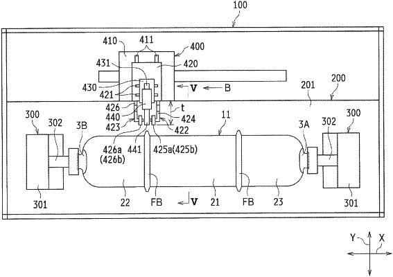
1. A weld bead cutting device configured to cut a weld bead generated on an outer circumference of a welding portion, the weld bead being generated when end edges of two resin members are abutted on and welded to each other, each of the end edges having a ring shape on an open side, the weld bead cutting device comprising:
a rotation mechanism configured to rotate a workpiece formed as at least the two resin members are welded to each other, the workpiece being rotated around a rotation axis that extends along an abutting direction of the at least two resin members;
a cutting tool arranged on an outer peripheral side of the workpiece and configured to cut the weld bead;
at least two pressing rotors arranged on opposite sides of the cutting tool, the pressing rotors being configured to be pressed against an outer peripheral surface of the workpiece; and
a reciprocation unit configured to hold the cutting tool and the pressing rotors and reciprocate the cutting tool and the pressing rotors relative to the workpiece along a direction orthogonal to the rotation axis,
wherein the pressing rotors are arranged at four locations that surround a position where the cutting tool is arranged, and outer surfaces of the pressing rotors on a side facing the outer peripheral surface of the workpiece are positioned on a virtual plane extending in a same diretion as the rotation axis,
wherein, the at least two pressing rotors are arranged on opposite sides of the cutting tool, so that, in a side view, a height positin at which the cutting tool is located is lower than a height position of an upper side of the at least two pressing rotors and the height position at which the cutting tool is located is higher than a height position of a lower side of the at least two pressing rotors.
|