| CPC B01D 45/16 (2013.01) [B04C 3/06 (2013.01); F01D 5/189 (2013.01); F01D 9/065 (2013.01); F02C 6/08 (2013.01); F02C 7/052 (2013.01); F02C 7/18 (2013.01); B04C 2003/003 (2013.01); B04C 2003/006 (2013.01); F02K 3/04 (2013.01); F05D 2260/607 (2013.01); Y02T 50/60 (2013.01)] | 20 Claims |

|
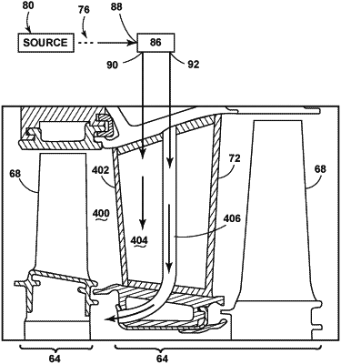
1. A turbine engine comprising:
a compressor section which receives an ambient air stream and emits a compressed stream;
a combustion section which receives the compressed stream and emits a combustion stream which is at a higher temperature than the compressed stream;
a turbine section which receives the combustion stream and emits an exhaust stream which is at a lower temperature than the combustion stream;
a rotatable drive shaft coupling a portion of the turbine section with a portion of the compressor section and defining a rotational axis for the turbine engine;
a bypass conduit coupling the compressor section to the turbine section while bypassing at least the combustion section to supply either a portion of the ambient air stream or a portion of the compressed stream to the turbine section to define a bypass stream;
at least one particle separator fluidly coupled to the bypass stream, the at least one particle separator having:
a separator inlet receiving the bypass stream;
a separator outlet fluidly coupled with the turbine section to output a reduced-particle stream that is provided to the turbine section for cooling; and
a particle outlet receiving a concentrated-particle stream comprising separated particles;
at least one stationary vane located within the turbine section, wherein the at least one stationary vane includes a root and a tip at least partially defining an interior; and
a conduit passing through the interior of the at least one stationary vane from the tip to the root and isolated from the interior, wherein the conduit is in fluid communication with the particle outlet for receiving the concentrated-particle stream from the at least one particle separator.
|