| CPC A63B 60/54 (2015.10) [A63B 53/0412 (2020.08); A63B 53/0433 (2020.08); A63B 53/0475 (2013.01); A63B 2053/0479 (2013.01); A63B 2209/00 (2013.01)] | 22 Claims |

|
1. A clubhead for an iron-type golf club, comprising:
an iron-type body having a heel portion, a toe portion, a top-line portion, a rear portion, a face portion, a sole portion extending rearwardly from a lower end of the face portion to a lower portion of the rear portion, a cavity defined by a region of the body rearward of the face portion, forward of the rear portion, above the sole portion and below the top-line portion, wherein:
the face portion includes an ideal striking location that defines the origin of a coordinate system in which an x-axis is tangential to the face portion at the ideal striking location and is parallel to a ground plane when the body is in a normal address position, a y-axis extends perpendicular to the x-axis and is also parallel to the ground plane, and a z-axis extends perpendicular to the ground plane, wherein a positive x-axis extends toward the heel portion from the origin, a positive y-axis extends rearwardly from the origin, and a positive z-axis extends upwardly from the origin;
the face portion defines a striking face plane that intersects the ground plane along a face projection line;
the body includes a central region which extends along the x-axis from a location greater than about −25 mm to a location less than about 25 mm;
the face portion, within the central region, having a minimum face thickness no less than 1.0 mm and a maximum face thickness of no more than 3.5 mm;
the sole portion contained within the central region includes a thinned forward sole region located adjacent to the face portion and within a distance of 17 mm measured horizontally in the direction of the y-axis from the face projection line, and a thickened rearward sole region located behind the thinned forward sole region, with the thinned forward sole region defining a sole wall having a minimum forward sole thickness of no more than 3.0 mm and less than the maximum face thickness;
the top-line portion contained within the central region includes a thinned undercut region located adjacent to the face portion and within a distance of 17 mm measured horizontally in the direction of the y-axis from the face projection line, the thinned undercut region defining a top-line wall having a minimum undercut thickness of no more than 3.0 mm and less than the maximum face thickness; and
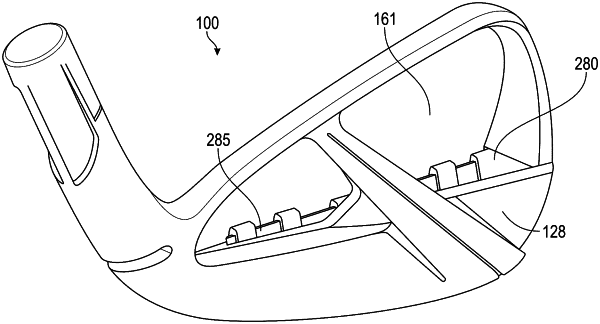
a damper positioned within the cavity and extending from the heel portion to the toe portion, wherein:
a front surface of the damper includes three or more front relief portions; and
the front surface of the damper contacts a rear surface of the face portion between the three or more front relief portions.
|