| CPC A63B 53/0429 (2020.08) [A63B 53/0412 (2020.08); A63B 53/0487 (2013.01); A63B 53/0445 (2020.08)] | 20 Claims |

|
1. A putter-type golf club head comprising:
a body comprising:
a heel portion;
a toe portion distal from the heel portion;
a top rail;
a sole portion distal from the top rail; and
a striking surface forming a recess defined by the heel portion, the toe portion, the top rail, and the sole portion of the body;
a striking surface imaginary vertical axis that extends through a geometric center of the striking surface relative to the heel portion, the toe portion, the top rail, and the sole portion; and
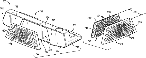
an insert configured to be received within and complimentary with the recess defined by the striking surface;
wherein:
the insert comprises a first material and a second material forming at least one of a front surface adapted for impact with a golf ball, a rear surface opposite the front surface, and a second material thickness defined as a distance between the front surface and the rear surface;
the insert further defines a plurality of circular-shaped voids that extend through an entirety of the second material thickness;
wherein the plurality of circular-shaped voids are arranged in a plurality of rows extending in a heel-to-toe direction and a plurality of columns extending in a top rail-to-sole direction;
wherein a horizontal center-to-center distance between adjacent circular-shaped voids within a given row increases from the striking surface imaginary vertical axis toward the heel portion and the toe portion;
wherein the horizontal center-to-center distance between adjacent circular-shaped voids is governed by the equation:
Hi=H1*BH(i-1)
wherein:
Hi is the horizontal center-to-center distance between a give pair of adjacent circular-shaped voids; and
BH is a constant greater than 1.
|