| CPC A61B 17/645 (2013.01) [A61B 17/62 (2013.01); A61B 17/6425 (2013.01); A61F 5/0195 (2013.01); A61B 2017/00407 (2013.01); A61B 17/1796 (2013.01); A61B 17/8897 (2013.01)] | 8 Claims |

|
1. A fixation system, comprising:
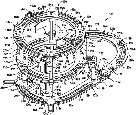
a plurality of rings, each ring having a first face, a second face, and at least one slot penetrating from the first face to the second face; a plurality of members joining each one of the plurality of rings to an adjacent one of the plurality of rings;
a rocker plate assembly having a unitary U-shaped body including a first side member, a second side member, and a curved portion attached to the first side member opposite a first end and attached to the second side member opposite a second end, wherein the first and second side members each have at least one T-shaped slot defined from a top surface of the unitary U-shaped body, wherein the top surface further includes a plurality of scallop-shaped recesses adjacent each side of each of the at least one T-shaped slot; and
a plurality of sliders, each slidably retained in a respective bottom of a respective one of the T-shaped slots of the first and second side members, a first shaft slidably retained in a respective top of the respective one of the T-shaped slots of the first and second side members, a support portion attached to the first shaft, and a second shaft attached to the support portion, the second shaft offset from the first shaft.
|