| CPC A01F 12/22 (2013.01) [A01F 7/02 (2013.01); A01D 41/02 (2013.01); A01D 89/002 (2013.01); A01F 12/10 (2013.01); A01F 12/20 (2013.01); A01F 12/32 (2013.01)] | 9 Claims |

|
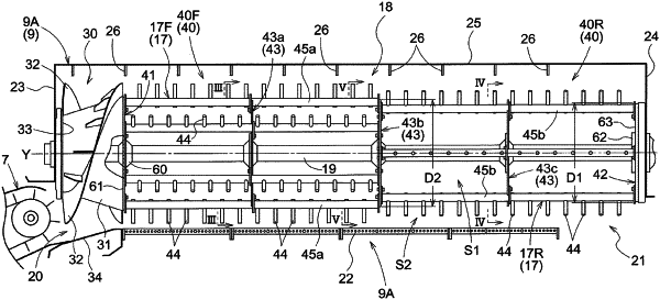
1. A threshing cylinder comprising:
a threshing cylinder support shaft that is rotatably provided in a threshing chamber into which the entirety of harvested crops is fed, so as to be oriented along a front-rear direction of the threshing chamber;
a raking section that is supported by a front portion of the threshing cylinder support shaft and that rakes the fed crops toward a rear of the threshing chamber; and
a threshing processing section that is supported by a portion of the threshing cylinder support shaft located rearward of the raking section and that performs threshing processing on the crops raked by the raking section,
wherein the threshing processing section comprises:
a front support member that is supported by the threshing cylinder support shaft;
a rear support member that is supported by a portion of the threshing cylinder support shaft located rearward of the front support member;
an intermediate support member that is supported by a portion of the threshing cylinder support shaft located between the front support member and the rear support member;
a plurality of bar-shaped threshing teeth support members that are supported by the front support member, the intermediate support member, and the rear support member in a state in which the threshing teeth support members extend along the threshing cylinder support shaft and are spaced in a circumferential direction of the threshing processing section; and
a plurality of bar-shaped threshing teeth that are supported by each of the plurality of threshing teeth support members in a state in which the threshing teeth protrude outward in a radial direction of the threshing processing section from the threshing teeth support member and are spaced in a direction extending along the threshing cylinder support shaft,
wherein each of the plurality of threshing teeth support members is divided into a front-side divided threshing teeth support member located forward of the intermediate support member, and a rear-side divided threshing teeth support member located rearward of the intermediate support member, and
wherein in a circumferential direction of the threshing processing section, the plurality of front-side divided threshing teeth support members have the same arrangement pitch, the plurality of rear-side divided threshing teeth support members have the same arrangement pitch, and an arrangement of the front-side divided threshing teeth support members and an arrangement of the rear-side divided threshing teeth support members are different, and in the circumferential direction of the threshing processing section, all intervals between the front-side divided threshing teeth support member and the rear-side divided threshing teeth support member adjacent thereto are equal.
|