| CPC H10N 50/85 (2023.02) [G06F 7/523 (2013.01); H10N 50/80 (2023.02); H01F 10/3286 (2013.01); H03K 19/20 (2013.01)] | 20 Claims |

|
1. A multiplier comprising:
a continuous bottom layer of ferromagnetic material separated from a plurality of regions of ferromagnetic material positioned on a plane substantially parallel to the continuous bottom layer;
a thin electrically conductive layer positioned between the continuous bottom layer and the plurality of regions of ferromagnetic material, the thin electrically conductive layer sufficient to induce a reciprocal anti-ferromagnetic response between one of the regions of ferromagnetic material to a corresponding coupled area of the continuous bottom layer of ferromagnetic material;
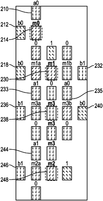
the plurality of regions of ferromagnetic material arranged as a sparse rectangular array of ferromagnetic regions in a first column, second column, third column, fourth column, and fifth column, the sparse rectangular array having a first row, second row, third row, fourth row, fifth row, sixth row, seventh row, eighth row, ninth row, and tenth row;
the plurality of regions of ferromagnetic material further comprising:
a plurality of input ferromagnetic regions for application of a magnetic field having an orientation parallel to the thin electrically conductive layer, the input ferromagnetic regions comprising:
a first a0 input ferromagnetic region, a second a0 input ferromagnetic region, a first a1 input ferromagnetic region, a second a1 input ferromagnetic region, a first b0 input ferromagnetic region, a second b0 input ferromagnetic region, a third b0 input ferromagnetic region, a first b1 input ferromagnetic region, a second b1 input ferromagnetic region, and a third b1 input ferromagnetic region;
a plurality of output regions configured to generate an output according to an orientation of a magnetic field in a respective region, the output regions comprising:
an m0 output ferromagnetic region, an m1 output ferromagnetic region, an m2 output ferromagnetic region, and a plurality of m3 output ferromagnetic regions comprising a first m3 output ferromagnetic region, a second m3 output ferromagnetic region, and a third m3 output ferromagnetic region;
a plurality of fixed value ferromagnetic regions, the fixed value ferromagnetic regions having either a one value or a zero value;
where a one magnetic value in a particular region corresponds to a magnetic field having a first direction and a zero magnetic value corresponds to a magnetic field in the particular region having a second direction opposite the first direction;
the first row having the first a0 input ferromagnetic region at the second column;
the second row having the first b0 input ferromagnetic region at the first column and the m0 output ferromagnetic region at the second column;
the third row having a zero ferromagnetic region in the second and fourth columns and a one ferromagnetic region in the third column;
the fourth row having the second b0 input ferromagnetic region at the first column, the m1 output ferromagnetic region at the third column, and the first b1 input ferromagnetic region at the fifth column;
the fifth row having the first a1 input ferromagnetic region at the second column, a zero ferromagnetic region at the third column, and the second a0 input ferromagnetic region at the fourth column;
the sixth row having the second b1 input ferromagnetic region at the first column, the first m3 output ferromagnetic region at the third column, and the third b0 input ferromagnetic region at the fifth column;
the seventh row having a zero ferromagnetic region at the second and fourth columns, and the second m3 output ferromagnetic region at the third column;
the eighth row having the second a1 input ferromagnetic region at the second column and the third m3 output ferromagnetic region at the third column;
the ninth row having the b1 input ferromagnetic region at the first column, the m2 output ferromagnetic region at the third column, and a one ferromagnetic region at the fourth column;
the tenth row having a zero ferromagnetic region at the second column;
and where the first and second a0 input ferromagnetic region, the first and second a1 input ferromagnetic regions, the first, second, and third b0 input ferromagnetic regions, and the first, second, and third b1 input ferromagnetic regions are configured to perform mathematical multiplications by application of a magnetic field oriented in the first direction for a logic one and by application of a magnetic field in the second direction for a logic zero;
the multiplier configured to generate output values as a magnetic field direction of:
the m0 output ferromagnetic region,
the m1 output ferromagnetic region, and;
at least one of the first, second, and third m3 output ferromagnetic regions.
|