| CPC H05B 47/18 (2020.01) [F21S 4/28 (2016.01); F21V 5/007 (2013.01); F21V 7/0091 (2013.01); F21V 7/04 (2013.01); F21V 23/06 (2013.01)] | 36 Claims |

|
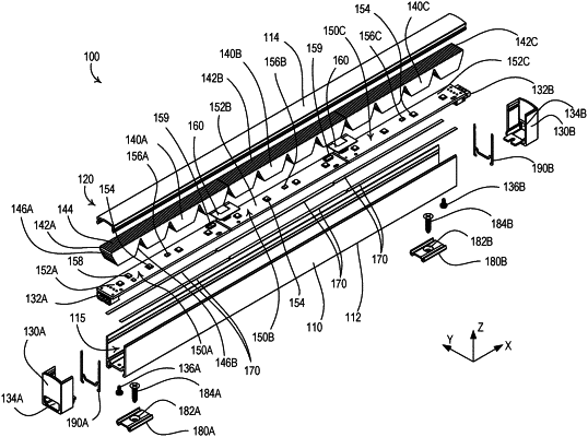
1. A linear lighting device comprising:
an elongated housing defining a cavity extending along a longitudinal axis of the housing;
a plurality of emitter printed circuit boards configured to be received within the cavity of the housing; and
a plurality of emitter modules mounted to each of the plurality of emitter printed circuit boards;
wherein each of the plurality of emitter printed circuit boards has a control circuit mounted thereto, the control circuit configured to control the plurality of emitter modules mounted to the respective emitter printed circuit board based on receipt of one or more messages, and
wherein at least one of the plurality of emitter printed circuit boards has a serial communication circuit mounted thereto, the serial communication circuit configured to communicate the one or more messages via a serial communication bus, and
wherein each of the plurality of emitter printed circuit boards has a drive circuit mounted thereto, the drive circuit configured to:
receive a DC bus voltage on a DC power bus for powering the plurality of emitter printed circuit boards; and
conduct drive currents through the plurality of emitter modules mounted to the respective emitter printed circuit board.
|