| CPC H05B 45/46 (2020.01) | 24 Claims |

|
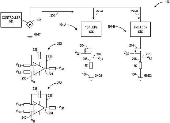
1. A circuit for sharing current between parallel LED pathways, the circuit comprising:
a first LED pathway comprising:
a first set of LEDs, the first set of LEDs comprising one or more first LEDs;
a first transistor coupled to the first set of LEDs and configured to control a first current through the first set of LEDs by altering a first conductivity between a first source and a first drain based on a first voltage applied to a first gate of the first transistor; and
a first measurement node comprising a first sensed voltage;
a second LED pathway comprising:
a second set of LEDs, the second set of LEDs comprising one or more second LEDs;
a second transistor coupled to the second set of LEDs and configured to control a second current through the second set of LEDs by altering a second conductivity between a second source and a second drain based on a second voltage applied to a second gate of the second transistor; and
a second measurement node comprising a second sensed voltage;
a first differential amplifier configured to compare the first sensed voltage to the second sensed voltage and to output the first voltage, wherein the first voltage is applied to the first gate of the first transistor, wherein the first differential amplifier is configured to affect the first current through the first set of LEDs by altering the first conductivity between the first source and the first drain, wherein the first differential amplifier comprises a first inverting input coupled to the first measurement node and a first non-inverting input coupled to the second measurement node, wherein one of the inputs of the first differential amplifier is coupled to a bias node; and
a second differential amplifier configured to compare the second sensed voltage to the first sensed voltage and to output the second voltage, wherein the second voltage is applied to the second gate of the second transistor, wherein the second differential amplifier comprises a second inverting input coupled to the second measurement node and a second non-inverting input coupled to the first measurement node, wherein one of the inputs of the second differential amplifier is coupled to the bias node, wherein the second differential amplifier is configured to affect the second current through the second set of LEDs by altering the second conductivity between the second source and the second drain.
|