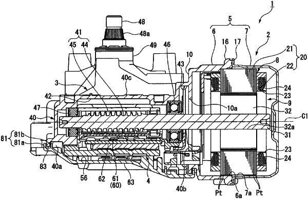
| CPC H02K 1/278 (2013.01) [B60S 1/08 (2013.01); H02K 7/1166 (2013.01); H02K 21/16 (2013.01); H02K 29/03 (2013.01)] | 3 Claims |

|
1. A rotor, comprising:
a shaft rotating around a rotational axis;
a rotor core fixed to the shaft and rotating with the rotational axis as a center in a radial direction;
a plurality of permanent magnets arranged side by side in a circumferential direction on an outer circumferential surface of the rotor core; and
a plurality of salient poles formed in a rectangular shape that is long in the radial direction as viewed from a direction of the rotational axis, protruding outward in the radial direction from the outer circumferential surface of the rotor core, and arranged between the permanent magnets adjacent to each other in the circumferential direction,
wherein an arc center of the outer circumferential surface of the rotor core between the plurality of salient poles is displaced outward in the radial direction and off-centered from the rotational axis in a manner that a center in the circumferential direction between the salient poles adjacent to each other in the circumferential direction on the outer circumferential surface of the rotor core protrudes to an outermost side in the radial direction,
the permanent magnet has an inner circumferential surface in an arc shape on an inner side in the radial direction as viewed from the direction of the rotational axis, and an outer circumferential surface in an arc shape on an outer side in the radial direction as viewed from the direction of the rotational axis, and is formed line-symmetrically with the center in the circumferential direction as a center,
an arc center of the inner circumferential surface of the permanent magnet is displaced outward in the radial direction and off-centered from the rotational axis so as to correspond to the outer circumferential surface of the rotor core,
an angle formed by side surfaces facing each other of two salient poles adjacent to each other in the circumferential direction is the same as an angle formed by side surfaces on both sides in the circumferential direction of the permanent magnet facing the side surfaces of the salient poles in the circumferential direction, and
when a distance between the outer circumferential surface of the rotor core and an outermost end of the salient pole in the radial direction is Lt and a distance between the inner circumferential surface of the permanent magnet and an outermost end in the radial direction on the side surface of the permanent magnet is Lme, the distances Lt and Lme are set to satisfy Lme<Lt.
|