| CPC G01V 1/50 (2013.01) [E21B 49/0875 (2020.05); E21B 2200/20 (2020.05); G01V 2210/1299 (2013.01); G01V 2210/1429 (2013.01); G01V 2210/6222 (2013.01)] | 13 Claims |

|
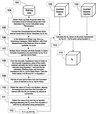
1. An analytical method to predict fluid saturation Sfl in a subsurface reservoir comprising the following steps:
using a first acoustic impedance (102) and a first P- to S-wave velocity ratio (103) inverted from seismic data, and at least one nearest well providing three well-logging probes measuring three different parameters (101) selected so that:
a) a product of P-wave velocity of sound obtained from a first well-logging probe with density data obtained from a second well-logging probe and target fluid in sedimentary rocks represents a second acoustic impedance,
b) a third well-logging probe obtains S-wave velocity of sound and produces measurement signals hereby modified to a second P- to S-wave velocity ratio (107) developing in opposite directions to each other due to target fluid variation, on one hand, and water content, on another hand, in the sedimentary rocks, and
c) the three well-logging probes being further selected so that resulting pairs within an acoustic impedance and P- to S-wave velocity ratio plane correspond to an equal fluid saturation, associated respectively with the sedimentary rocks comprising a given percentage of rock matrix or water, are equally represented by one pair of values of representative parameters of 100% fluid saturation, creating a system of sets of pairs of values of the representative parameters, to obtain a continuous representation of fluid saturation of a formation of interest penetrated by the at least one nearest well,
the analytical method characterised by:
d) calibrating a brine saturated rock trend within the formation of interest (110), simultaneously obtaining a cementation factor ‘n’ and a mineralogy factor ‘G’ to further use in calculations,
e) calibrating a first fluid saturation computed from the second acoustic impedance and P- to S-wave ratio curves with a second fluid saturation obtained from a conventional method by iterating a P-wave velocity ‘Vpfl’ and a density ‘ρfl’ of the target fluid, therefore obtaining values for the P-wave velocity ‘Vpfl’ and the density ‘ρfl’ (111) to further use in the calculations,
f) inverting the seismic data to obtain the first acoustic impedance (102) and the first P- to S-wave velocity ratio (103),
g) estimating the fluid saturation Sfl (114) using a calibrated rock physics model by inputting corresponding data (113), whereby Sfl=1−Sw, wherein Sw is water saturation.
|