| CPC G01F 1/588 (2013.01) | 19 Claims |

|
1. A magnetic-inductive flow meter for measuring flow velocity or volume flow rate of a medium, the flow meter comprising:
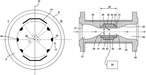
a measuring tube having a first cross-sectional area and configured to convey the medium in a longitudinal direction defined by a measuring tube axis, wherein:
the measuring tube has an inlet side end plane and an outlet side end plane, which bound the measuring tube in the longitudinal direction;
the measuring tube includes between inlet side and outlet side end planes a middle segment, which has a second cross-sectional area, wherein the first cross-sectional area is greater than the second cross-sectional area;
a vertical measuring tube longitudinal plane divides the measuring tube into a first side and a second side; and
the measuring tube includes a fluid conveying passageway, which includes a wall bounded by a liner;
at least one magnetic field generator configured to generate a magnetic field in the medium extending essentially perpendicularly to the longitudinal direction, wherein the at least one magnetic field generator includes a pole shoe or a saddle coil, and wherein, in the second cross-sectional area of the measuring tube, the pole shoe or the saddle coil subtends the fluid conveying passageway with a maximum central angle; and
an electrode system including at least two electrode pairs, which are adapted to register a voltage induced perpendicularly to the magnetic field and to the longitudinal direction between the electrode pairs, wherein:
a first electrode of each electrode pair is disposed on the first side of the measuring tube;
a second electrode of each electrode pair is disposed on the second side of the measuring tube;
a central angle in the second cross-sectional area of the measuring tube defines a minimum circular sector in which electrodes of the at least two electrode pairs that are disposed on a same side of the measuring tube are distributed; and
the at least two electrode pairs are arranged in the middle segment,
wherein the central angle and the maximum central angle are configured relative to each other such that the flow meter is to a degree insensitive to departures from a rotationally symmetric flow such that the flow meter in a test measurement has a measurement error of flow velocity defined by
 and/or a measurement error of volume flow rate defined by
 less than 1.0%, wherein:
uva and uS are flow velocities, and Vva and VS are volume flow rates of the medium;
the flow velocity uva and the volume flow rate Vva form reference values; and
the flow velocity uS and/or the volume flow rate VS are determined in the case of a rotationally unsymmetric flow.
|