| CPC F28F 1/40 (2013.01) [B21C 37/207 (2013.01); F28F 13/12 (2013.01)] | 21 Claims |

|
1. A system comprising a fluid process heat exchange rod for heating or cooling fluid in a process vessel, comprising:
an elongated outer jacket extending along an axis defining a closed distal end and an open proximal end, an inner cavity defined within the outer jacket;
a manifold attached to the proximal end of the outer jacket, the manifold having two connectors providing fluid communication with the inner cavity, a first connector being offset from a centerline through the manifold and a second connector being located along the centerline and aligned with the outer jacket axis;
an elongated polymer flow diverter positioned within the inner cavity, the flow diverter extending from the manifold to a point spaced from the closed distal end such that a distal space is formed in the inner cavity between the flow diverter and the closed distal end, the flow diverter having a central inner bore extending the length of the flow diverter and being in fluid communication with the second connector to fluidly connect the second connector and the distal space, the flow diverter also having an outer surface defined by two parallel helical flutes that extending the length of the flow diverter and having an outer diameter approximately equal to an inner diameter of the outer jacket so as to be in contact therewith, the helical flutes defining two parallel helical grooves spaced inward from the inner diameter of the outer jacket that forms two parallel flow passages between the flow diverter and the outer jacket fluidly connecting the first connector and the distal space; and
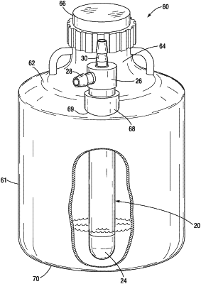
a process vessel adapted for holding fluid, the process vessel having an upper wall, wherein the heat exchange rod is mounted to the upper wall of the process vessel such that the closed distal end of the outer jacket extends downward toward a bottom of a main portion of the process vessel so as to be submerged in fluid within the process vessel, wherein the outer jacket of the heat exchange rod has a length sufficient such that the closed distal end extends to within 1 inch of the lower floor of the vessel,
wherein the heat exchange rod is configured such that fluid flowing into the second connector passes distally through the inner bore to the distal space, and returns proximally from the distal space through the at least one helical flow passage to the first connector, and fluid flowing into the first connector passes distally through the at least one helical flow passage to the distal space, and returns proximally from the distal space through the inner bore to the second connector, the fluid flowing through the heat exchange rod therefore being adapted to heat or cool fluid within the process vessel.
|