| CPC F17C 13/004 (2013.01) [B65D 90/027 (2013.01); B65D 90/041 (2013.01); B67D 7/38 (2013.01); B67D 7/58 (2013.01); B67D 9/00 (2013.01); F17C 3/04 (2013.01); B65D 2588/12 (2013.01); F17C 2203/012 (2013.01); F17C 2203/0358 (2013.01); F17C 2205/0355 (2013.01); F17C 2209/22 (2013.01); F17C 2221/033 (2013.01); F17C 2223/0161 (2013.01); F17C 2260/011 (2013.01); F17C 2270/0107 (2013.01)] | 19 Claims |

|
1. A fluid-tight and thermally insulating tank wall, comprising:
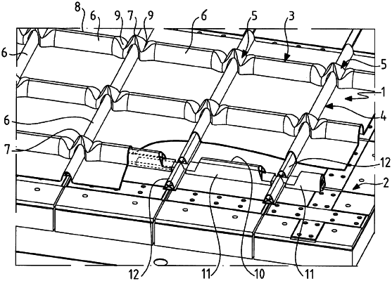
a thermally insulating barrier and a corrugated fluid-tight membrane, the thermally insulating barrier having a support surface, the corrugated fluid-tight membrane including a first series of parallel corrugations and a second series of parallel corrugations and plane portions situated therebetween that rest on the support surface of the thermally insulating barrier, said first and second series of parallel corrugations extending in intersecting directions and forming a plurality of nodes at intersections thereof, and
wave reinforcements being arranged under the corrugations of the first series of corrugations,
wherein two successive wave reinforcements in a corrugation of the first series of corrugations each include a sole including a lower wall resting on the support surface of the thermally insulating barrier and a reinforcement portion disposed above the sole in a thickness direction of the tank wall, the two wave reinforcements—being developed longitudinally in the corrugation on either side of a node,
said soles being hollow, a hollow portion of said soles having a plane section parallel to the support surface of the thermally insulating barrier, a connecting member extending in said corrugation at a level of the node and being nested in the soles of said two wave reinforcements in such a manner as to assemble the two wave reinforcements in an aligned position, and an end of the connecting member nested in said sole having a plane section extending parallel to said lower wall, said end of the connecting member having a width, the width being measured in a direction perpendicular to a longitudinal direction of said corrugation and perpendicular to the thickness direction of the tank wall, the width being greater than a thickness of said end of the connecting member, the thickness of said end of the connecting member being measured in the thickness direction of the tank wall.
|