| CPC F16K 11/0712 (2013.01) [F16K 3/24 (2013.01); F16K 11/0716 (2013.01)] | 10 Claims |

|
1. A spool-type switching valve, comprising:
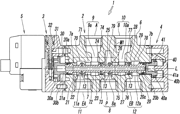
a spool hole extending in an axial direction to which at least a pair of channels through which compressed fluid flows is connected; a spool inserted in the spool hole so as to be movable in the axial direction; and a valve drive member that operates the spool in the axial direction to switch a state of communication between the channels,
wherein the spool includes a land portion including a ring-shaped sliding portion around an outer periphery about an axis and a small-diameter portion smaller in outside diameter than the land portion next to each other in the axial direction,
wherein the sliding portion of the land portion has a ring-shaped recessed groove that is open in a radial direction, and a ring-shaped packing made of an elastic material is housed in the recessed groove,
wherein, in an inner surface of the spool hole, a ring-shaped valve seat at which the land portion is fitted slidably in the axial direction, with the sliding portion facing the inner surface, and a ring-shaped large-diameter portion that is larger in inside diameter than the valve seat are formed next to each other in the axial direction, and the pair of channels are connected to opposite sides of the valve seat in the axial direction,
wherein communication between the pair of channels can be switched by an operation of the spool between a state in which the land portion is disposed at the large-diameter portion and the small-diameter portion is disposed at the valve seat so that the pair of channels communicate with each other and a state in which the land portion is disposed at the valve seat so that the communication between the pair of channels is blocked,
wherein the ring-shaped recessed groove includes a groove bottom and a pair of side wall surfaces, wherein the groove bottom includes an upstream end disposed at, of the pair of channels, a channel through which compressed fluid flows into the spool hole in the axial direction and a downstream end disposed at a channel through which the compressed fluid flows out of the spool hole when the pair of channels communicate with each other, and
wherein the pair of side wall surfaces are vertically erected from the upstream end and the downstream end of the groove bottom and opposed to each other, wherein the groove bottom of the recessed groove includes an inclined surface having an axial length at least half as long as an axial length of the groove bottom and the inclined surface continuously decreases in diameter from the upstream end to the downstream end,
wherein an inner periphery of the packing is brought into pressure-contact with the groove bottom with stress concentration at a pressure contact point that defines an end at the upstream end of the inclined surface,
wherein an angle θ that a connection surface connecting the pressure contact point and the upstream end of the groove bottom forms with the axis is within a range of 0°≤0≤α, where α is an angle that the inclined surface forms with the axis, and
wherein the inner periphery of the packing has a linear shape parallel to the axis in a cross section of the packing in a state not mounted in the recessed groove.
|