| CPC F02C 9/18 (2013.01) [F01D 17/105 (2013.01); F02K 3/06 (2013.01); F05D 2220/32 (2013.01); F05D 2240/12 (2013.01); F05D 2260/606 (2013.01)] | 16 Claims |

|
1. A gas turbine engine comprising:
a bypass duct extending about a longitudinal centerline of the gas turbine engine, the bypass duct including at least one bypass duct wall defining at least a portion of a bypass flow path through the bypass duct, the at least one bypass duct wall forming a scoop extending into the bypass flow path relative to surrounding portions of the at least one bypass duct wall that are upstream and downstream of the scoop;
a bleed conduit including an inlet connected to the scoop of the at least one bypass duct wall, the inlet surrounded by the scoop;
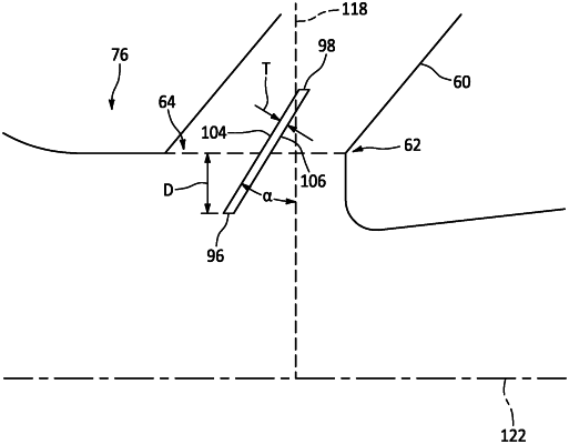
and at least one louver extending between a first lateral side and a second lateral side opposite the first lateral side, each of the first lateral side and the second lateral side mounted to the bleed conduit, the at least one louver further extending between a leading edge and a trailing edge opposite the leading edge, the leading edge located within the bypass flow path and the trailing edge located within the bleed conduit;
wherein the scoop forming a portion of the bypass duct wall includes 1) an upstream scoop portion that extends into the bypass flow, the upstream scoop portion having a first upstream scoop end that is a location on the upstream scoop portion, and 2) a downstream scoop portion that extends into the bypass flow, the downstream scoop portion having a second upstream scoop end that is a location on the downstream scoop portion, wherein the upstream scoop portion is upstream of the bleed conduit and the downstream scoop portion is downstream of the bleed conduit and wherein the second upstream end located on the downstream scoop portion extends a greater distance into the bypass flow than the first upstream scoop end located on the upstream scoop portion; and
wherein the leading edge of the at least one louver is positioned substantially at an imaginary line intersecting the first upstream end and the second upstream scoop end such that the leading edge extends into the bypass flow path less than second upstream scoop end.
|