| CPC F02B 55/14 (2013.01) [F01C 1/063 (2013.01); F02B 77/00 (2013.01)] | 11 Claims |

|
1. A biaxial supporting device for a rotary opposed piston engine, comprising:
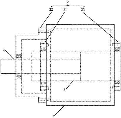
a cylinder body (1), wherein the interior of the cylinder body (1) has a cavity (11), and two opposite wall sides are provided with a first axle hole (12) and a second axle hole (13);
a fixing component (2), wherein the fixing component (2) is fixed on the outer side wall of the cylinder body (1) and corresponds to the first axle hole (12);
a thick axle (3), wherein the thick axle (3) penetrates through the first axle hole (12) and is rotatably connected with the first axle hole (12), and the thick axle (3) is provided with a coaxial through hole (31);
a thin axle (4), wherein the thin axle (4) is in transition fit with the through hole (31);
one end of the thin axle (4) penetrates through the through hole (31) and is rotatably connected with the fixing component (2), and the other end has a shoulder (41); and
one end of the shoulder (41) is abutted against the end surface of the thick axle (3) located inside the cavity (11), and another end of the shoulder (41) extends out of the cavity (11) through the second axle hole (13).
|