| CPC F01D 9/023 (2013.01) [F01D 11/005 (2013.01); F02C 7/28 (2013.01); F05D 2240/12 (2013.01); F05D 2240/35 (2013.01); F05D 2240/55 (2013.01); F05D 2260/30 (2013.01)] | 10 Claims |
|
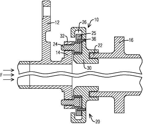
1. A gas turbine sealing interface to seal a gap between a transition duct and a turbine section component, comprising:
an outlet exit frame of the transition duct including a fastener hole;
a first stage turbine vane structure including an upstream lip;
a seal coupling the outlet exit frame to the first stage turbine vane structure, an upstream portion of the seal includes a U-shaped cross section forming a first groove, wherein a downstream portion of the seal comprises a second groove; and
an L-shaped rail including a flat portion and a lipped portion disposed perpendicularly to the flat portion, the flat portion includes a counterbore, the counterbore including a through-hole that mates to the fastener hole, the L-shaped rail is secured to the outlet exit frame by a fastener inserted in the through-hole and the fastener hole, the lipped portion of the L-shaped rail extending radially in respect to a flow path, and the upstream lip of the first stage turbine vane structure is engaged in the second groove, the fastener including a bolt head,
wherein the first groove receives the lipped portion of the L-shaped rail, wherein the seal is secured to the outlet exit frame via the L-shaped rail, wherein the bolt head is configured to be recessed within the counterbore
wherein the seal overlaps the counterbore along an axial length of the counterbore in a direction of the flow path.
|