| CPC E04F 15/02038 (2013.01) [B26D 3/065 (2013.01); E04C 2/40 (2013.01); E04F 15/102 (2013.01); E04F 15/107 (2013.01); E04F 2201/0146 (2013.01); E04F 2201/0161 (2013.01); E04F 2201/0176 (2013.01); E04F 2201/042 (2013.01); E04F 2201/043 (2013.01)] | 15 Claims |

|
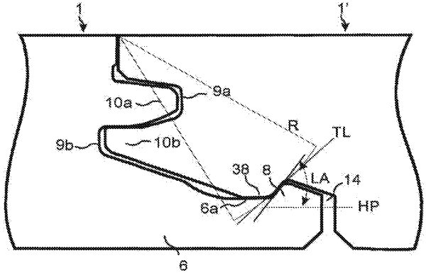
1. A set of floor panels provided with a mechanical locking system and comprising a first panel and a second panel, the second panel being configured to be locked to the first panel by angling, wherein the mechanical locking system comprises:
a strip extending horizontally from a lower part of a first edge of the first panel and a downwardly open locking groove formed in a second edge of the second panel, the strip comprising an upwardly protruding locking element configured to cooperate with the locking groove for locking the first edge and the second edge in a horizontal direction parallel to a main plane of the floor panels,
an upper tongue and a lower tongue configured to cooperate with an upper tongue groove and a lower tongue groove, respectively, for locking the first edge and the second edge vertically at least in a first direction upwards, and
a lower protrusion provided in the second edge of the second panel configured to contact a contacting surface of an upper part of the strip for locking the first edge and the second edge in a second vertical direction downwards,
wherein the contacting surface is inclined upward toward the locking element or is substantially horizontal,
wherein the locking element includes a locking surface extending from and angled with respect to the contacting surface of the upper part of the strip, the locking surface being located between the contacting surface of the upper part of the strip and an upper part of the locking element, and
wherein the upper tongue is spaced from an upper wall of the upper tongue groove in a locked position of the first edge and second edge.
|