| CPC D06F 58/206 (2013.01) [D06F 58/04 (2013.01); D06F 58/20 (2013.01); D06F 2103/40 (2020.02); D06F 2103/50 (2020.02); D06F 2105/26 (2020.02)] | 19 Claims |

|
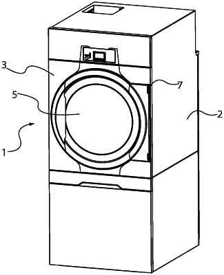
1. Tumble dryer comprising a housing, a drum in the housing accessible from a front side of the housing and rotatable about its center axis, a fan arrangement for producing a flow of process air passing through the drum, and a heat pump for drying the process air before entering the drum, the heat pump comprising a compressor, a condenser, an expansion valve, and an evaporator forming a refrigerant fluid loop, wherein:
the rotatable drum comprises a circular rear wall with air inlet openings and a radial cylindrical wall with air outlet openings,
the compressor is adapted to be run by an inverter, allowing the compressor output to be varied,
the expansion valve is controllable, and
the expansion valve and the compressor are controlled by a controller based on data from at least one sensor,
wherein the at least one sensor comprises one or more of a first pressure sensor, a second pressure sensor, a first temperature sensor, and a second temperature sensor, wherein the first pressure sensor and the first temperature sensor are located in the refrigerant fluid flow from the expansion valve to the compressor, and the second pressure sensor and the second temperature sensor are located in the refrigerant fluid flow from the compressor to the expansion valve.
|