| CPC B65H 31/10 (2013.01) [B65H 31/20 (2013.01); B65H 31/3054 (2013.01); B65H 31/32 (2013.01); B65H 2403/41 (2013.01); B65H 2405/323 (2013.01); B65H 2405/324 (2013.01); B65H 2511/12 (2013.01)] | 20 Claims |

|
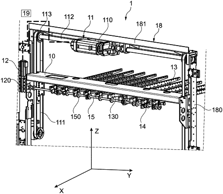
1. A separator for temporarily receiving sheet elements that are to be transferred from a stacking table to an output conveyor of bundles of sheet elements, the separator comprising:
a support mounted and configured to slide in a vertical direction;
a drive device for driving the support in the vertical direction;
a plurality of arms extending in a longitudinal horizontal direction, spaced apart in a transverse direction, at least one arm of the plurality of arms being mounted and configured to move in the longitudinal horizontal direction with respect to the support, a movement of the at least one arm modifying an overhanging length of the at least one arm with respect to the support on a first side in the longitudinal horizontal direction; and
a drive system configured to simultaneously move the at least one arm in the longitudinal horizontal direction and to keep another of the plurality of arms in a longitudinal position, the drive system including:
a shaft, the shaft being deployed in the transverse direction and driven in rotation;
a pinion for each arm of the plurality of arms, each pinion for each arm rotating with the shaft;
a rack secured to the plurality of arms; and
a clutch-forming device configured to selectively couple and uncouple each pinion for each arm with respect to the rack,
wherein the clutch-forming device includes, for each arm, an actuator configured to move a pinion associated with an arm translationally along an axis of the shaft in order to selectively engage or disengage the rack with respect to the arm.
|