| CPC B65D 63/1081 (2013.01) | 8 Claims |

|
1. A clip, comprising:
a holding base configured to hold an attaching article; and
a connecting base integrated with the holding base and including a bolt introduction hole that is configured such that a bolt member formed on an object member is introduced thereinto,
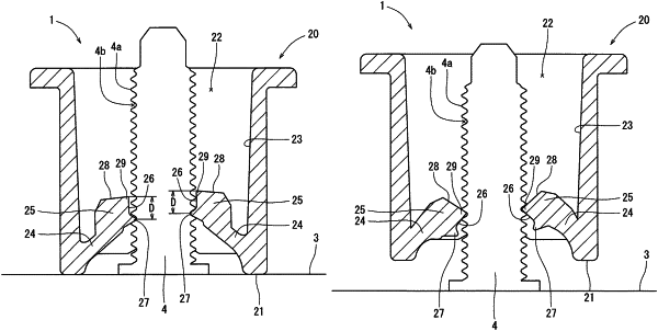
wherein the connecting base includes flexible engagement strips formed on an inner surface thereof and having pressing blocks formed on distal ends thereof,
wherein the engagement strips are oppositely projected from the inner surface of the connecting base toward a center of the bolt introduction hole,
wherein the pressing blocks respectively include engagement claws formed on proximal end portions of inner surfaces thereof and configured to engage predetermined portions of a thread groove of the bolt member when the bolt member is introduced into the bolt introduction hole,
wherein when the bolt member is introduced into the bolt introduction hole, the engagement claws engage the predetermined portions of the thread groove of the bolt member, so that the connecting base is connected to the object member,
wherein in a connected condition in which the connecting base is connected to the object member, when the engagement strips are flexed due to an extraction force applied to the connecting base, thereby disengaging the engagement claws from the predetermined portions of the thread groove of the bolt member, in place of the engagement claws, edge portions formed on distal end portions of the inner surfaces of the pressing blocks engage different portions of the thread groove of the bolt member that are positioned away from the predetermined portions of the thread groove corresponding to the engagement claws in a direction toward a distal end of the bolt member, and
wherein a distance between the engagement claw and the edge portion of each pressing block is equal to approximately once or twice a thread pitch of the bolt member.
|