| CPC B60R 13/0846 (2013.01) [F01N 1/026 (2013.01); F02M 35/1266 (2013.01); F02M 35/1283 (2013.01); G10K 11/161 (2013.01); G10K 11/172 (2013.01)] | 14 Claims |

|
1. A broadband resonator, comprising:
a resonator insert configured for installation into an interior of an air duct casing or an air inlet or outlet port casing of a filter housing, the resonator insert comprising:
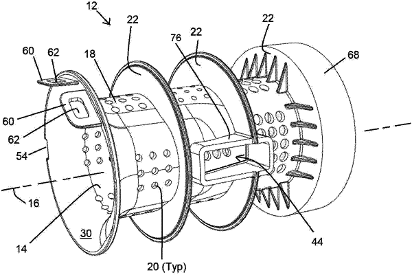
a tubular pipe elongated along a central axis from a first axial end to a second axial end of the broadband resonator insert, the tubular pipe having a circumferential outer wall having a plurality of perforation holes spaced apart and extending radially through the circumferential outer wall,
wherein an interior of the tubular pipe forms a gas flow duct for guiding a gas flow through the broadband resonator from the first axial end to the second axial end;
a plurality of annular disk-shaped walls provided on and projecting radially outwardly from the circumferential outer wall of the tubular pipe, adjacent ones of the annular disk-shaped walls spaced axially part from each other to define resonator chambers therebetween;
wherein a first one of the plurality of the annular disk-shaped walls is arranged proximate to the first axial end of the resonator insert;
wherein a bell mouth is formed at the second axial end of the tubular pipe, the bell mouth flared radially outwardly;
a resonator casing formed in an interior of an air duct, or by the air duct or in a filter housing air inlet port or air outlet port, the resonator casing having an interior chamber configured to receive the resonator insert, the resonator casing comprising:
a resonator insert receiving chamber radially outwardly delimited by a stepped circumferential wall;
wherein the stepped circumferential wall forms one or more steps, the steps formed by an abrupt change in inner diameter of the stepped circumferential wall;
wherein the one or more steps are positioned to close against an axial outer side of a respective one of the plurality of the annular disk-shaped walls of the resonator insert, the steps cooperating with the respective annular disk-shaped wall to divide an annular volume of the resonator insert receiving chamber surrounding the tubular pipe into separate resonator chambers;
wherein the steps and the plurality of annular disk-shaped walls are positioned such that when the resonator insert is fully received into the resonator insert receiving chamber, the steps close against its respective annular disk-shaped wall of the resonator insert;
wherein the resonator insert further includes:
an air flow sensor opening extending through the circumferential outer wall of the tubular pipe, the air flow sensor opening configured to receive a mass air flow sensor through the air flow sensor opening and projecting into the gas flow duct in the interior of the tubular pipe; and
a radially outward projecting circumferential outer wall formed on the tubular pipe and surrounding the air flow sensor opening.
|