| CPC B60L 53/20 (2019.02) [B60L 53/16 (2019.02); B60L 53/18 (2019.02); H02J 7/0045 (2013.01); H02P 27/06 (2013.01); B60K 6/28 (2013.01); B60Y 2200/91 (2013.01); B60Y 2200/92 (2013.01); B60Y 2300/91 (2013.01); H02J 2207/20 (2020.01)] | 20 Claims |

|
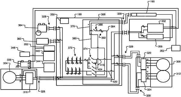
1. A battery charging system, comprising:
an electric motor including stator coils;
a battery;
a charge port configured to receive power from charging stations by wire;
first and second electrical conductors connected between the battery and the charge port;
an inverter module including (a) inputs connected to receive power from the battery and (b) outputs connected to U, V, and W phases of the electric motor and configured to output positive reference potentials to the electric motor;
a third electrical conductor; and
a switch configured to electrically connect and disconnect a first end of the third electrical conductor to and from the first electrical conductor,
wherein the third electrical conductor includes a second end that is directly connected to the U phase of the electric motor and one of the outputs of the inverter module.
|
|
19. A battery charging system, comprising:
an electric motor including stator coils;
a battery;
a charge port configured to receive power from charging stations by wire;
first and second electrical conductors connected between the battery and the charge port;
a third electrical conductor; and
a switch configured to electrically connect and disconnect a first end of the third electrical conductor to and from the first electrical conductor,
wherein the third electrical conductor includes a second end that is directly connected to (a) the U phase of the electric motor and (b) one output of a group of outputs of an inverter module, the outputs of the inverter module connected to U, V, and W phases of the electric motor and configured to output positive reference potentials to the electric motor.
|
|
20. A battery charging method, comprising:
receiving power from a charging station by wire using a charge port;
electrically connecting a battery with the charge port via first and second electrical conductors;
by an inverter module, receiving power from the battery and outputting power to via outputs of the inverter module to U, V, and W phases of an electric motor, the electric motor including stator coils, and the outputs configured to output positive reference potentials to the electric motor; and
by a switch, electrically connecting and disconnecting a first end of a third electrical conductor to and from the first electrical conductor,
wherein the third electrical conductor includes a second end that is directly connected to the U phase of the electric motor and one of the outputs of the inverter module.
|