| CPC B60L 53/12 (2019.02) [H01F 27/288 (2013.01); H01F 27/2823 (2013.01); H01F 27/36 (2013.01); H01F 27/361 (2020.08); H01F 27/363 (2020.08); H01F 27/366 (2020.08); H01F 38/14 (2013.01); H02J 7/0013 (2013.01); H02J 7/0044 (2013.01); H02J 50/12 (2016.02); H02J 50/70 (2016.02); H02J 50/90 (2016.02); H04B 5/0031 (2013.01); H04B 5/0037 (2013.01); H04B 5/0087 (2013.01); H04W 4/80 (2018.02); H02J 50/23 (2016.02)] | 19 Claims |

|
1. A system for wireless charging comprising:
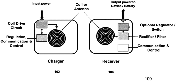
a charger including a charger coil comprising a copper material and having a substantially planar surface, a thin magnetic planar layer located under the charger coil, and a charger drive circuit including resonant capacitors to supply an alternating current to the charger coil;
a receiver unit including a receiver coil coupled to a receiver electronics including one or more resonant capacitors, a rectifier circuit, and smoothing capacitors wherein the receiver unit is coupled to a mobile device for providing power or charging the mobile device;
wherein the receiver coil is a solenoid comprising a ferrite core with a relative magnetic permeability exceeding 1, and with copper Litz wire wrapped around the ferrite core along a winding axis to form a wound wire section and with the ferrite core extending beyond the wound wire section along the winding axis and terminating in a first end and a second end with the distance between the first end and the second end defining the length of the solenoid; and
with the first end and the second end each having a smaller dimension in either axis of the end that is smaller than the length of the solenoid; and
wherein the charger coil is patterned in a spiral or similar shape defining a charger coil area wherein the charger coil area is larger than an area of the first end and an area of the second end; and
when the charger coil is driven by the charger drive circuit with the alternating current, an inductive magnetic field in a direction substantially perpendicular to the planar surface of the charger coil, at the surface of the charger coil at a center of the charger coil area is generated; and
wherein when the receiver coil is placed above and near the surface of the charger coil in a charging position, the magnetic flux from the charger coil is guided through the ferrite core of the receiver coil and returns to close a magnetic loop through the charger magnetic planar layer to transfer power to the receiver unit.
|