| CPC B25J 9/0054 (2013.01) [G03F 7/70725 (2013.01); G03F 7/70775 (2013.01)] | 9 Claims |

|
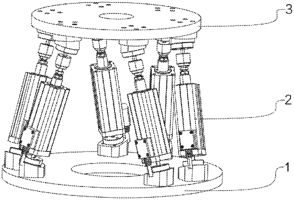
1. A nanoscale positioning apparatus with a stroke greater than a micron-scale movement and multiple degrees of freedom, comprising a base, a plurality of parallel branch chain mechanisms and a working table; wherein
two sides of the plurality of parallel branch chain mechanisms are connected to the base and the working table through a first plurality of hinge base supporting pieces and a second plurality of hinge base supporting pieces, respectively;
each of the parallel branch chain mechanisms comprises an electric cylinder, a micro-motion drive mechanism, a laser interferometer, a grating measuring device, a self-locking upper hinge and a self-locking lower hinge;
a top of the base is connected to a first end of the electric cylinder through the self-locking lower hinge;
a second end of the electric cylinder is connected to a first end of the micro-motion drive mechanism;
a second end of the micro-motion drive mechanism is connected to a bottom of the working table through the self-locking upper hinge;
and
the grating measuring device is provided on the electric cylinder,
wherein
the self-locking upper hinge comprises a first spherical-hinge base and a second spherical-hinge base;
the first spherical-hinge base is hinged to the bottom of the working table through a first pin shaft;
a first side of the first spherical-hinge base is provided with a first fixed arc groove, and a second side of the first spherical-hinge base is connected to an electromagnet;
the second spherical-hinge base is hinged to the bottom of the working table through a second pin shaft;
one side of the second spherical-hinge base is provided with a second fixed arc groove;
a steel ball is provided in the first fixed arc groove and the second fixed arc groove;
the first spherical-hinge base is provided with a first through hole, and the second spherical-hinge base is provided with a second through hole;
a pull rod is provided in the first through hole and the second through hole;
a first end of the pull rod is hinged to the second spherical-hinge base through a third pin shaft;
a second end of the pull rod is exposed out of the first through hole, and a magnetic plate is provided at the second end of the pull rod;
one end of the magnetic plate is located on a side of the electromagnet;
a spring is provided between the first spherical-hinge base and the magnetic plate; and
a lower end portion of the steel ball is connected to an upper end of the micro-motion drive mechanism.
|