| CPC B23Q 11/001 (2013.01) [B23Q 15/14 (2013.01); B23Q 17/2233 (2013.01); G05B 19/251 (2013.01); G05B 19/404 (2013.01); B23Q 2220/006 (2013.01); G05B 2219/49169 (2013.01); G05B 2219/49186 (2013.01)] | 17 Claims |

|
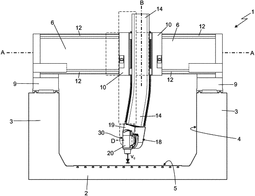
1. A numerical-control machine tool (1) comprising: a tool-holder head (30) which is provided with a tool-holder spindle (20) and is capable of rotating/tilting said tool-holder spindle (20) about two different rotation axes (C, D) inclined to one another; a movable supporting structure (2, 3, 6, 10, 14; 101, 104, 107) that supports the tool-holder head (30) and is provided with moving members (7, 11, 15) adapted to move, during machining of the piece, the tool-holder head (30) in the space surrounding the piece to be machined; an electronic control device (21) that commands the moving members of the movable supporting structure (7, 11, 15) and the moving members of the tool-holder head (17) so as to move, during the machining of the piece, the tool-holder head (30) and the tool-holder spindle (20) in the space around the piece to be machined in order to carry out the planned machining in automatic manner; and one or more inclinometer micro sensors (22) that are located on the movable supporting structure (2, 3, 6, 10, 14; 101, 104, 107) of the machine tool, next to said tool-holder head (30), and are adapted to measure/determine the tilt of the element on which the same one or more inclinometer microsensors are mounted, relative to a reference inertial plane immobile in the space;
the machine tool being characterised in that the electronic control device (21) is electronically connected to said one or more inclinometer microsensors (22), and is additionally programmed/configured to command the moving members of the movable supporting structure (7, 11, 15) and the moving members of the tool-holder head (17) also based on the signals arriving from said one or more inclinometer microsensors (22), so as to correct/change, in real time during the machining of a piece, the programmed spatial position and orientation of the tool-holder spindle (20) in order to compensate a possible error in the spatial position and/or orientation of the tool-holder head (30) resulting from a deformation of the movable supporting structure (2, 3, 6, 10, 14; 101, 104, 107) of the machine tool.
|