| CPC A61M 39/10 (2013.01) [A61B 17/00 (2013.01); A61B 17/11 (2013.01); A61M 1/3655 (2013.01); A61M 39/0247 (2013.01); A61M 39/04 (2013.01); A61M 39/12 (2013.01); A61M 39/14 (2013.01); A61B 2017/00477 (2013.01); A61B 2017/00685 (2013.01); A61B 2017/1107 (2013.01); A61B 2017/1132 (2013.01); A61M 2039/0258 (2013.01); A61M 2039/0273 (2013.01); A61M 2039/087 (2013.01)] | 21 Claims |

|
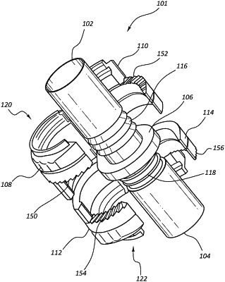
1. A vascular access system, comprising:
a first conduit;
a second conduit; and
a connector comprising an inside luminal wall, a first end, a second end, a first connecting member on the first end, and a second connecting member on the second end,
the connector being configured to couple to an end of the first conduit and to an end of the second conduit such that there is a continuous lumen from the first conduit to the second conduit, wherein the connector is configured to irreversibly couple to at least one of the first conduit and the second conduit,
wherein both the first and second connecting members further comprise a hinge,
wherein the connector comprises a flange disposed between the first end and the second end,
wherein the connector comprises a first circumferential ridge disposed on the first end adjacent the flange and a second circumferential ridge disposed on the second end adjacent the flange,
wherein each of the first and second circumferential ridges comprise a shoulder facing toward the flange,
wherein the first connecting member and the second connecting member each comprise a radially inwardly extending protrusion adjacent to the flange and comprising a shoulder facing away from the flange,
wherein at least a portion of the first conduit is disposed between the shoulder of the first circumferential ridge and the shoulder of the inwardly extending protrusion of the first connecting member when the first connecting member compresses the first conduit against the first end of the connector, and
wherein at least a portion of the second conduit is disposed between the shoulder of the inwardly extending protrusion of the second circumferential ridge and the shoulder of the second connecting member when the second connecting member compresses the second conduit against the second end of the connector.
|