| CPC A61M 25/09 (2013.01) [A61M 60/13 (2021.01); A61M 60/148 (2021.01); A61M 60/237 (2021.01); A61M 60/414 (2021.01); A61M 60/419 (2021.01); A61M 60/422 (2021.01); A61M 60/508 (2021.01); A61M 60/825 (2021.01); A61M 60/829 (2021.01); A61M 2205/3317 (2013.01); A61M 2205/3606 (2013.01); A61M 2205/366 (2013.01); A61M 2205/3666 (2013.01)] | 12 Claims |

|
1. A catheter assembly comprising:
a catheter body having a proximal catheter portion and a distal catheter portion;
a drive shaft extending through a first lumen defined in the catheter body; and
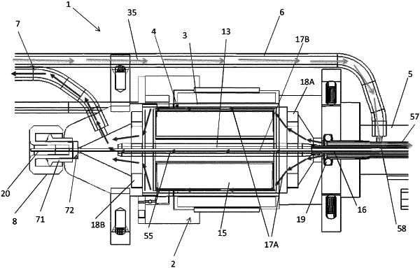
a motor assembly comprising:
a motor housing;
a stator and a rotor each enclosed in the motor housing, the rotor being electromagnetically coupled to the stator, wherein the rotor rotates in response to energizing the stator; and
a flow diverter positioned radially between the rotor and the stator in the motor housing, wherein the flow diverter comprises:
a rotor chamber within which the rotor is disposed;
a distal chamber and a proximal chamber positioned on opposing sides of the rotor chamber; and
at least one flange configured to mechanically couple the flow diverter to the motor housing;
wherein the at least one flange comprises a first flange positioned between the proximal chamber and the rotor chamber and a second flange positioned between the distal chamber and the rotor chamber, and wherein the first flange and the second flange are configured as dampers to isolate the motor assembly from external shock or vibrations.
|