| CPC A61B 1/008 (2013.01) [A61B 34/70 (2016.02); A61M 25/0133 (2013.01); A61B 2034/301 (2016.02); A61M 2025/0915 (2013.01); B25J 19/00 (2013.01)] | 11 Claims |

|
1. A bending and extending device, comprising:
an elastic hollow guide unit; and
a movable part to be movably inserted into the guide unit,
wherein:
the guide unit has a uniform cross-sectional shape and a uniform cross-sectional size along an entire length of the guide unit in which the movable part is inserted into the guide unit;
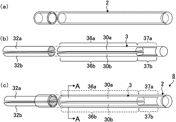
the movable part comprises a plurality of belt-like flexible parts and a distal end portion extending in a direction perpendicular to the flexible parts;
each flexible part has a divided range and a thin range that is thinner than the divided range, the thin ranges are positioned more closely to a distal end side of the flexible parts than the divided ranges;
the distal end portion connects the thin ranges of the flexible parts at distal ends of the flexible parts;
a combination of cross-sections of the divided ranges of the flexible parts has a same geometric shape as an internal cross-section of the guide unit;
the movable part causes the plurality of flexible parts to be bent in a direction perpendicular to an axial direction of the guide unit by sliding one of proximal ends of the plurality of flexible parts in the axial direction of the guide unit (hereinafter referred to as a flexible part sliding operation);
the distal ends of the flexible parts are inside the guide unit during the flexible part sliding operation;
when, by the flexible part sliding operation, a cross-section in which a contact point of a second flexible part of the flexible parts and an inner surface of the guide unit is present on an extending line extending from a line segment connecting the centroid of a first flexible part of the flexible parts and the axial center of the guide unit and in which the first flexible part and the second flexible part are directly or indirectly in contact with each other is generated, and when the cross-section is divided into two ranges by a predetermined straight line, the centroid of the first flexible part is not positioned in a range in which the contact point of the second flexible part and the inner surface of the guide unit is present; and
the predetermined straight line is a line that passes through the axial center of the guide unit, and that orthogonally crosses the extending line,
wherein, when the flexible parts are in a non-bent position, a thin range gap exists between the thin ranges and extends in the direction perpendicular to the axial direction, a divided range gap exists between the divided ranges and extends in the direction perpendicular to the axial direction, and the thin range gap is larger than the divided range gap in the direction perpendicular to the axial direction.
|