| CPC A47L 7/0004 (2013.01) [A47L 5/365 (2013.01)] | 12 Claims |
|
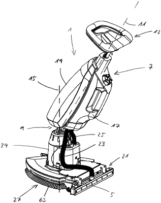
1. A floor cleaning machine comprising:
a base,
a cleaning element arrangement, held and driven on an underside of the base, the cleaning element arrangement being configured for engagement with a floor surface, wherein the cleaning element arrangement has at least one driven cleaning element, to which engagement elements for engagement with a floor surface to be cleaned are attached, wherein sections of the engagement elements which are provided for engagement with the floor surface extend in an engagement element plane,
an operating bar, attached to the base, for guiding and actuating the floor cleaning machine,
a suction foot, attached to the base or to the operating bar, the suction foot being configured for sucking up cleaning liquid from the floor surface,
a dirty water tank, attached to the base or to the operating bar, for receiving cleaning liquid taken up by the suction foot,
a suction turbine, which is attached to the base and has a suction turbine housing, which has an inlet opening and an outlet opening, wherein the suction turbine is configured to generate a suction air flow from the suction foot into the dirty water tank during operation, wherein the suction turbine is constructed in such a way that the suction air flow runs through the inlet opening towards the outlet opening, and
a separation container that adjoins the suction turbine housing, the suction container having an interior, which communicates with the inlet opening, an inlet, which communicates with the interior, and a bottom wall section facing the interior,
wherein, when viewed along a vertical axis running perpendicularly to the engagement element plane, the bottom wall section is arranged closer to the engagement element plane than the inlet opening, and
wherein a drainage opening leads out of the bottom wall section into the environment, which opening is provided with a valve, which is configured in such a way that it is closed when the suction turbine is in operation and open when the suction turbine is out of operation.
|