| CPC H02M 7/537 (2013.01) [H02M 1/08 (2013.01); H02M 7/487 (2013.01); H02M 1/0054 (2021.05)] | 20 Claims |

|
1. A power system comprising:
a plurality of power sources configured to be connected in one of a series connection, a parallel connection, or a combination of series and parallel connections, wherein the plurality of power sources are further configured to generate direct current (DC) power;
a storage device configured to store the DC power and discharge the stored DC power;
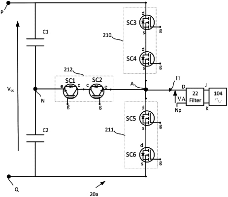
an inverter comprising:
a first input terminal;
a second input terminal;
an output terminal;
an input voltage midpoint node;
a first switch leg connected between the first input terminal and the output terminal, wherein the first switch leg comprises a first switch;
a second switch leg connected between the second input terminal and the output terminal, wherein the second switch leg comprises a second switch;
a third switch leg connected between the input voltage midpoint node and the output terminal; and
a controller configured to control the inverter to convert at least one of the DC power, generated by the plurality of power sources, or the stored DC power, discharged by the storage device, to an alternating current (AC) voltage, by:
during a first time period, disabling the second switch leg, and alternately enabling the first switch leg and the third switch leg; and
during a second time period, disabling the first switch leg, and alternately enabling the second switch leg and the third switch leg; and
a link unit connected between the plurality of power sources and the inverter and further connected to the storage device, wherein the link unit is configured to cause the storage device to be charged by the DC power from the plurality of power sources, and wherein the link unit is further configured to cause the storage device to discharge the stored DC power to the inverter.
|