| CPC H02K 5/225 (2013.01) [H02K 15/10 (2013.01); H02K 2203/06 (2013.01)] | 20 Claims |

|
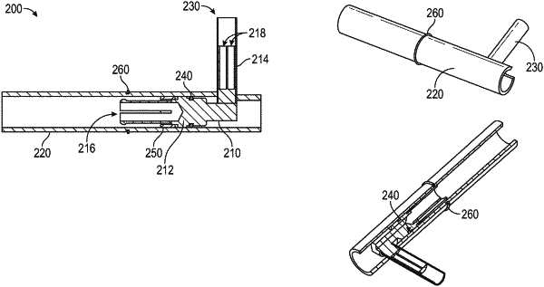
1. A terminal assembly for a stator, the terminal assembly comprising:
an elbow terminal comprising a first arm and a second arm disposed at 90 degrees relative to the first arm, the first arm configured to be connected to a lead wire and the second arm configured to be connected to a magnet wire; and
an insulating tube, wherein the first arm of the elbow terminal extends within the insulating tube and the second arm of the elbow terminal protrudes from the insulating tube;
wherein the terminal assembly further comprises at least one of:
a terminal nut disposed radially between the first arm and an inner surface of the insulating tube, wherein the terminal nut is configured to secure the elbow terminal within the insulating tube; or
a snap ring disposed on an outer surface of the insulating tube, wherein the snap ring is configured to secure the terminal assembly in an encapsulation tooling.
|