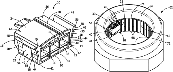
| CPC H02K 5/225 (2013.01) [H01R 13/506 (2013.01); H01R 13/631 (2013.01); H02K 15/0062 (2013.01); H01R 2201/10 (2013.01)] | 19 Claims |

|
1. An electrical connector comprising:
a housing having a front surface, a rear surface, and side surfaces;
a first wall extending between the front surface, the rear surface and the side surfaces;
a second wall extending between the front surface, the rear surface and the side surfaces, the second wall having a radiused reference surface;
an alignment projection extending from the radiused reference surface in a direction away from the first wall; and
a registration projection provided on the second wall and extending from the radiused reference surface in a direction away from the first wall, the registration projection being provided proximate the front surface.
|